Introduction
Servicing a keyboard assembly is a filthy business in many cases. Often, synths are stored without dust covers or have been gigged and the build up of FOD can be disgusting, especially when combined with Roland manufacturing over zealous lubrication. This dirt and lubricant is a hazard for the keyboard contacts and is to blame for many of the issues. See Jorick’s refurbishment article to see how challenging it can be, he made an overview of this installation process too.
Issues can also occur if it is simply the case that the keyboard has rarely been played, oxidisation of contacts over time happened in our case.
Important
It is essential to read the Roland Keyboard Assembly Guide
The keyboard contact arrangement in both old and new flexible PCBs is extremely sensitive! Dust and contaminants have to be prevented from entering the contact areas during assembly. The central datum point needs to be aligned carefully whilst first rubber contact strips are being placed around it to hold the assembly in position.
To ensure success PLEASE follow the instructions, it is a highly technical product that requires confidence and expertise when installing it. If something goes wrong or doesn’t work, it requires electronics skills.
This is a generic guide for repair and rebuild of this type of Roland keyboard used in many instruments.
Cleanliness is essential when fitting any keyboard contact PCB, the most common issues that cause problems in priority order are:
- Oil on particles from hands and fingers
- Dust
- Red epoxy glue used to secure weights in the keys (Roland batch issue)
- Silicone grease contamination
See our special page for an exhaustive examination of failure modes.
Rubber Contacts
See Roland Keyboard Assembly Guide for details on how to remove rubber contacts easily without damaging them.
It is essential to thoroughly clean contacts to remove microscopic dust particles before reassembly. Cleaning brand new contacts can slightly deteriorate contact resistance however it is still essential to confirm cleanliness and remove traces of dust using an anti-static brush or some kind of lint free wipe.
Dust causes uneven velocity pickup, or occasional mis-interpretation of velocity on one or more keys.
Red Glue
The red glue can be removed by soaking the keys in warm caustic soda solution used for cleaning drains. Take care not to let the solution exceed the melting point of plastic, there are reports of warped keys on various forums. It is a pretty nasty process but yields good results. There are various guides and forums on the web that detail this process, one of which is here.
Thoroughly cleaning all parts of the keyboard assembly is recommended.
Soldering
Some soldering and desoldering skills are needed if you want Aftertouch to work.
If in any doubt we can solder the connector to the correct position for you if you can tell us what Flexi type you have or send a picture.
The Aftertouch connector is no longer available. If you require this to work, the 2 pin connector needs to be transferred to the new board.
Ensuring Success
This page is focused on the important differences when installing the replacement Flexible PCB, plus any important points that ensure success and reliability. It is intended to supplement the Roland Service Notes that can be downloaded from an excellent no-fuss site www.synfo.nl, please make a donation if this site is useful to you.
The keyboard section of the Roland Service Notes is pretty thorough in it’s explanation. It gives plenty of warnings and tips on disassembly and reassembly.

As a whole, the keyboard assembly is quite complicated and contains many parts. We have created a more detailed guide for the keyboard assembly itself, Roland Keyboard Assembly Guide.
Read these guides fully before embarking on the disassembly and repair of the keyboard.
Identification
There are two types of Flexible circuits in use, it is important to identify which you have in order for us to provide the correct transition PCB if you require the connector pre-soldered or for the installer to solder the connector in the right position.
The most common on the Roland JD-800 is Type 1, it has a weak thermal connection and is most likely to fail. Type 2 has the Roland transition PCB mounted upside down. For Type 2, Transition PCB P0016A-04 is specially designed to rotate the signals to suit the different white flat cable.
The picture below shows how to identify the two types.

Instruments with Type 1 have a white flat cable with conductors exposed on opposite sides at each end of the cable. Type 2 has a white flat cable where the conductors are exposed on same side at each end of the cable. This means that the Mainboard flat cable connector has to be installed in a different position for Type 2, so that mounting of the new transition PCB is in the same orientation for all types.
If you have any doubt, please send us a picture and we will tell you what type it is. We can also solder the mainboard connector for you.
If you are replacing the white flat cable with a SynthParts equivalent, then use a type 2 installation method, pictures show full details in Keyboard PCB Resources.
Mainboard Cable Specification
| Type 1 | Type 2 | ||
| Conductors | 26 | 26 | |
| Length | 430 | 430 | mm |
| Pitch | 1.25 | 1.25 | mm |
| Thickness | 0.30 | 0.30 | mm |
| Width | 33.75 | 33.75 | mm |
| Connector Orientation |
B Opp Side |
A Same Side |
Remove Transition Board
Disconnect all cables and remove the transition board from it’s bracket. In the picture below, we temporarily covered the Aftertouch connector to protect it. The original fixing tape was in danger of touching the contact surfaces.
The bracket should be removed as well if using a strip of wood to hold the springs in place whilst working on the keyboard assembly.

Keyboard Assembly Guide
See Roland Keyboard Assembly Guide for details on techniques, disassembly & refitting the main keyboard assembly for all instruments.
Flat Cable & Connectors
The connector for the Aftertouch is reused as it is no longer available. It is ok to not connect it, it just won’t work. Mainboard flat cable connector can be reused as well, or we can provide a different but equivalent type.
Take care with the white flat cable, it can be easily damaged or contacts contaminated. Disconnect from keyboard assembly and leave connected to Mainboard -or- Remove, put to one side and refit last. If damaged, the white flat cable can be replaced with an IDC type, the method of which is covered in the build guide, Keyboard PCB Adaptors and Cable. When using a 30 way IDC cable method, the transition board needs to have a 30 way IDC cable header fitted instead of the main board connector, it is mounted to same side as where the bracket locates to.
There are other methods of flat cable replacement too, spares are available from Synthparts, we think that these require a type 2 connector position, contact us if you are trying this option. We supply a Molex ZIF 39-53-2264 connector on the transition PCB, that is perfect for this type of cable.
Aftertouch Connector
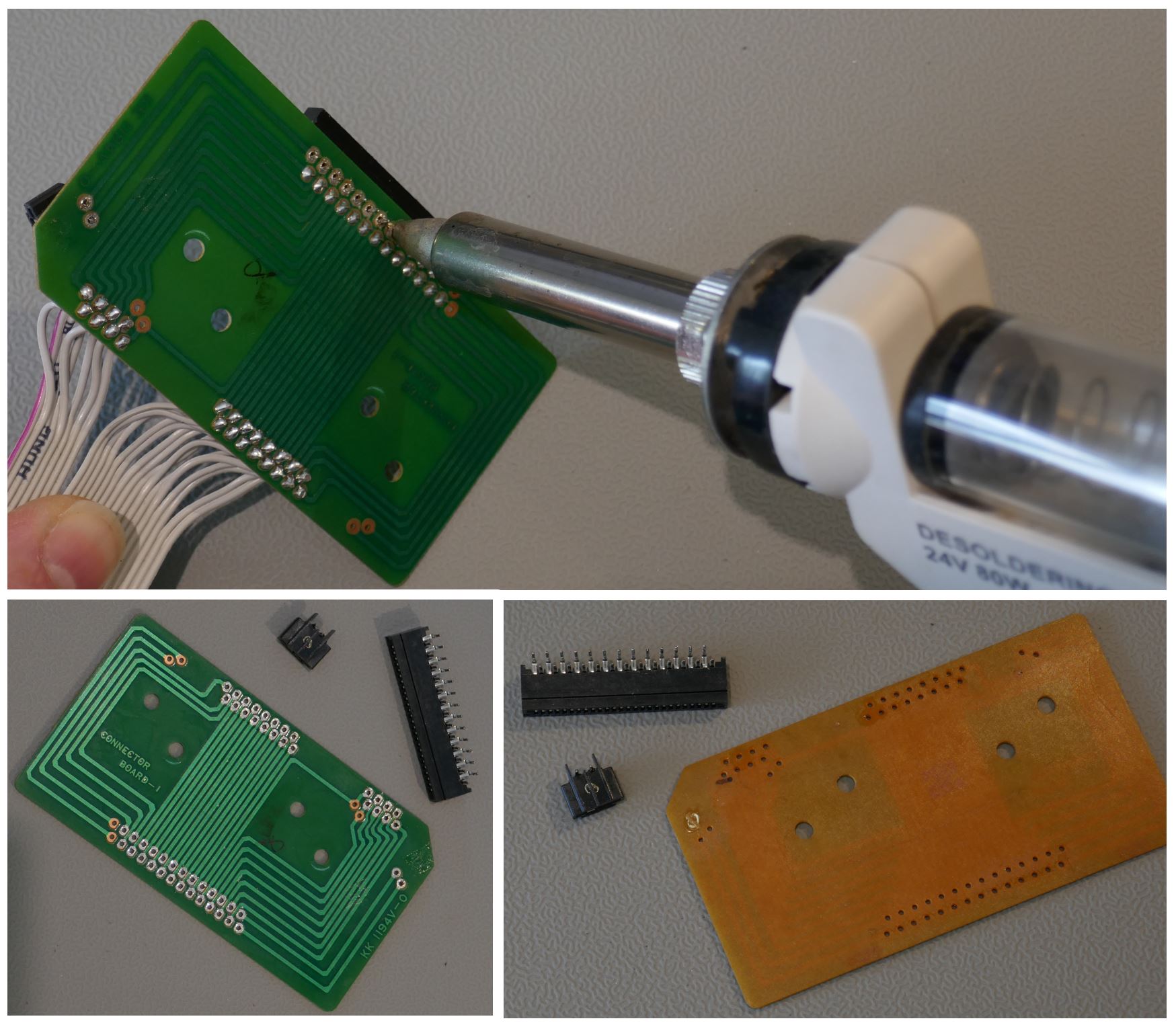
The old Aftertouch connector from the Roland transition board is removed by desoldering tool. Either electric, as shown in picture, or hand pump are used. It is straightforward because the PCB is single sided.
For early kits and prototypes, it is necessary to remove the mainboard connector too as a new one was not provided.
Fit Aftertouch Connector
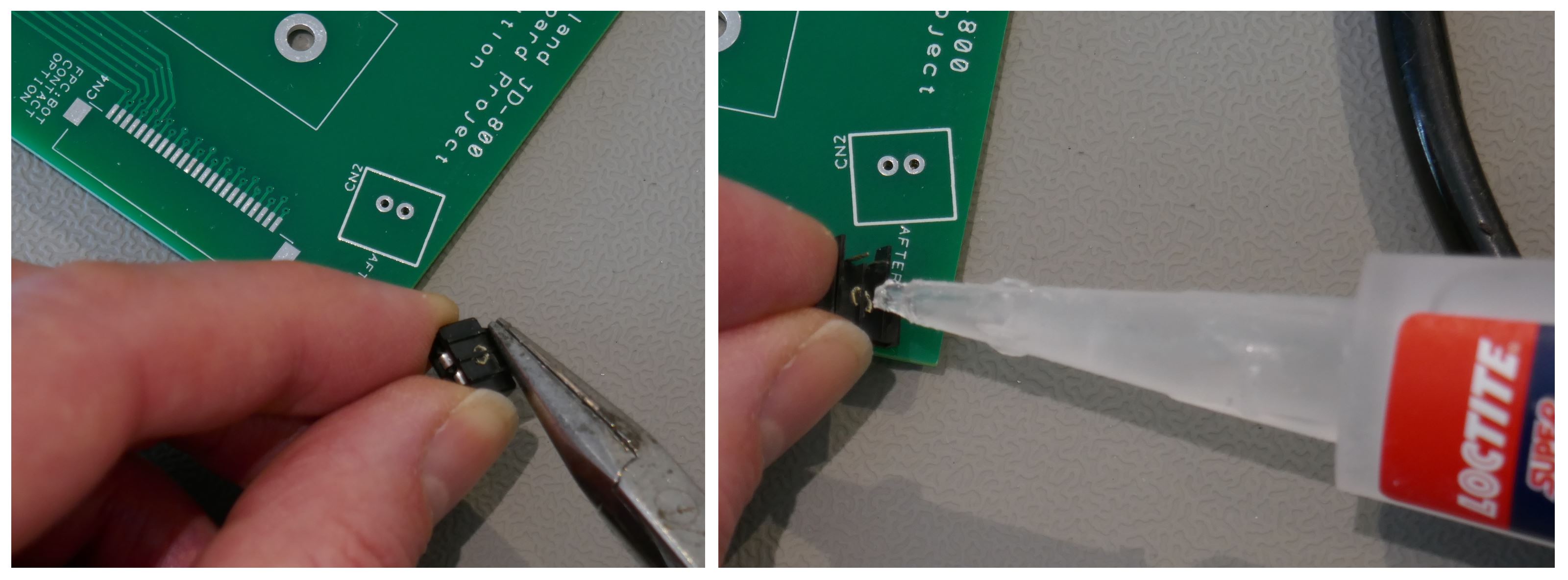
Fit the Aftertouch connector with a very small amount of superglue taking care not to contaminate the pins or contacts. It will be necessary to straighten the pins for a precise angled fit. If the glue bottle is full, transfer the glue to the connector with a cocktail stick or pin, it’s not worth the risk of flooding. Once done, leave it a while to set and solder the two pins.
Fit Mainboard Connector
If you have a connector provided by us, the replacement is white.
Note the positions for different connection methods, there is a high degree of flexibility to accommodate different instruments and issues:
- CN5 – Mounting position for Type 1 flexible cable connector.
- CN6 – Mounting position for Type 2 flexible cable on transition PCB P0016A-04.
- CN3 – Replacement Flat Cable Option using IDC should the flat cable be damaged.
- CN4 – Different type of FPC should Molex “Top Contact” type become obsolete.
- Dashed areas for CN5 or CN6 for Molex ZIF 39-53-2264 connector
Special note: Do not clean the flux from the white FPC connector. A non corrosive type for a no clean process is used. The danger of contaminants wicking into the contacts is very high. It is possible, but a very thorough washing process is required that is usually beyond hobbyist/service tech scope.
Type 1
Fit the mainboard connector on underside of PCB, on same side that bracket fits against. The PCB will look as shown in pictures below.

Type 2
The Mainboard connector is mounted on the top side of the transition PCB P0016A-04 as shown in the picture below. Contact us for an alternative solution before soldering if you do not have the correct PCB type.

Transition PCB
Fit the new transition PCB with both screws to the original position and plug in the Aftertouch flat cable into the 2 pin connector after cleaning contacts with IPA. The original securing tape will be very sticky, if this had touched the connection on the Aftertouch strip, remove sticky residue with IPA. Fitting the Flexible PCB into the locking “Zero insertion force” connector is shown in pictures below.
One user has reported that aftertouch required rotation of the aftertouch flexible strip by 180 degrees, other users have not. If aftertouch worked before and doesn’t work after this upgrade during testing, then refit rotated 180 degrees. See last section for important notes on this area. Note that contact areas are not well designed, usually this is the weak area that causes aftertouch to stop working completely.
It is a recommended to attach the mainboard white cable and Aftertouch to the PCB before mounting simply because it is easier to reach. Leave the flexi FPC connector until the board is mounted.
The picture below depicts Type 1. Type 2 has the mainboard connector mounted on top side of PCB and white cable is different.
Note: If both screws are not in position, the PCB could tilt and short the scan lines to the metalwork and potentially damage the scan chip. It does require an extreme angle but can happen during debugging/testing.
Mainboard Cable Installation
The white flat cable is reinstalled in exactly the same orientation as the Roland method. It is important that it is done correctly as there are many possible permutations that do not work. Note the signal naming on the transition board matches the mainboard, if necessary, these can be confirmed with the Roland service manual.
For both types of original flexible PCB, the transition board is mounted to the bracket in the same way and the blue stripe on the white flat cable always faces the green transition PCB.
Type 1
The mainboard connector is fitted on the underside of the transition PCB.
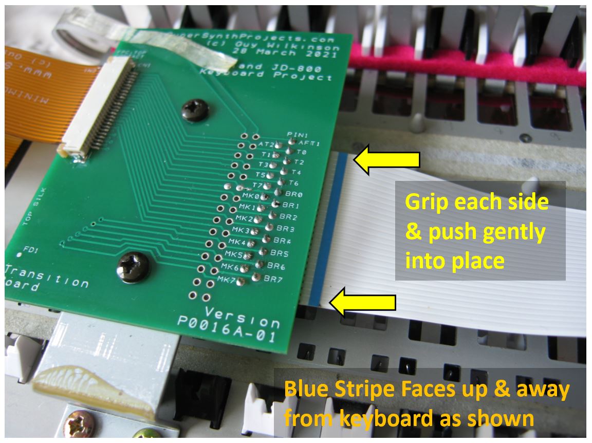
Fit the flat cable exactly as shown in picture below with blue stripe facing towards the green transition PCB, i.e. upwards away from the keyboard assembly. Picture shows the original “Push fit” connector type, see later for instructions if you have a Molex ZIF connector on transition boards P0016A-05 / -06.
Type 2
The mainboard connector is fitted on the top side of the transition PCB because the white flat cable contacts are on same side at each end.
Fit the flat cable in exactly same way as it was when removed from original Roland configuration; blue stripe facing towards the green transition PCB, i.e. facing the keyboard assembly. The pictures below show two different connector types for Type 2 keyboard configurations.

Many thanks to Brian in USA for these pictures, depicting the original black connector Roland used and Molex connectors. Brian did a fabulous job of fitting the flexi, getting it right first time.
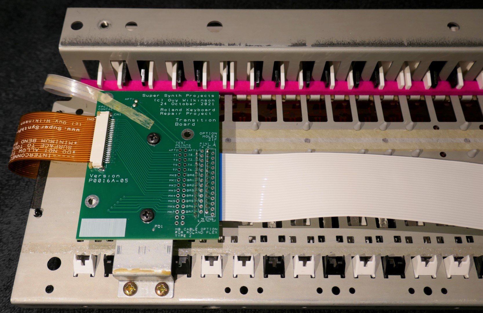
Mainboard Molex ZIF Option
The transition board P0016A-05 / -06 can accept a Molex ZIF 39-53-2264 connector. Instructions for it’s use are shown in the picture below.
If a pre-soldered connector was requested, it will be this one on future kits from 2022.
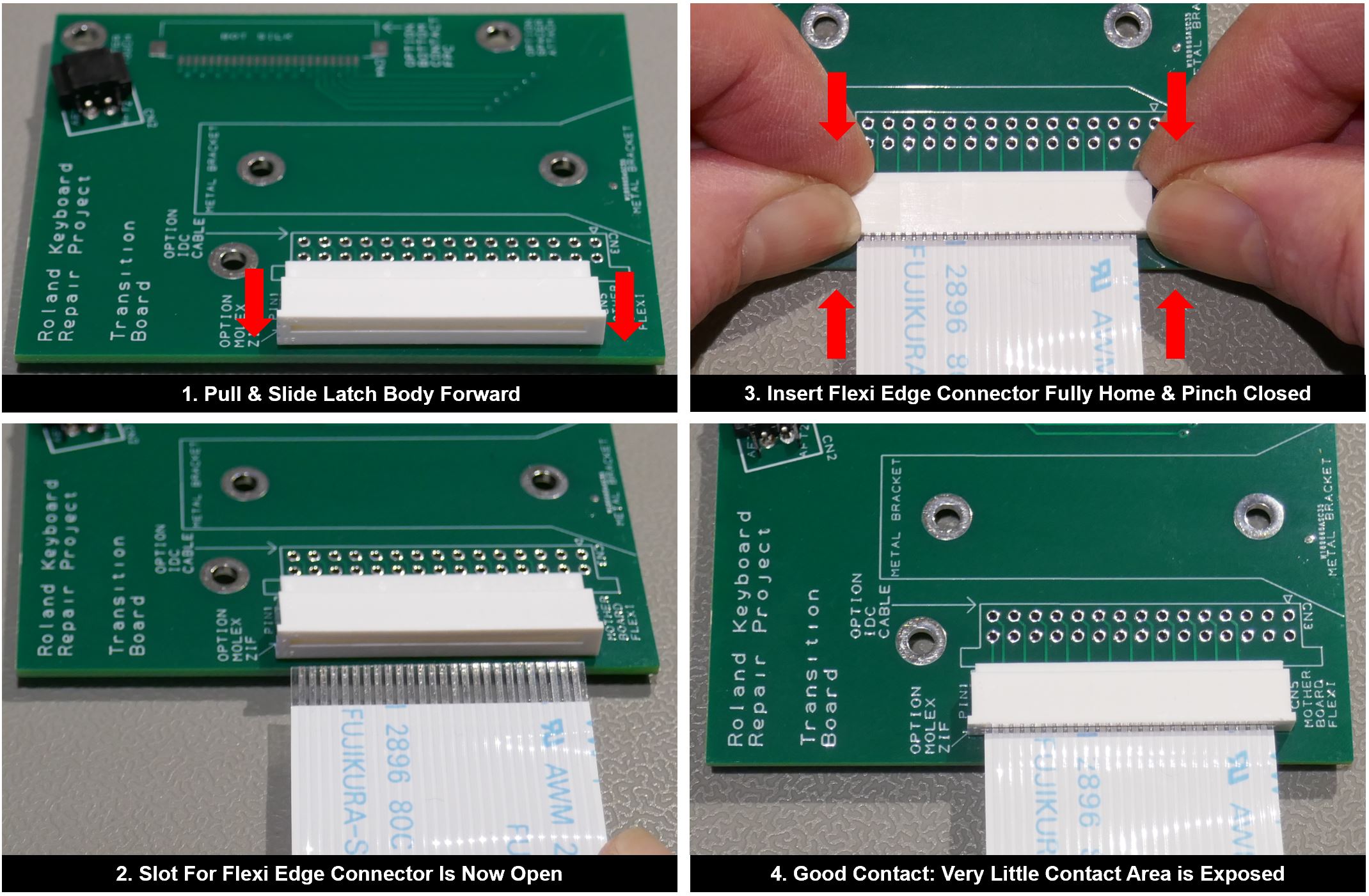
When soldering it in place, use the dashed silkscreen outline to place it in correct position for type 1 or 2 arrangements. Note that some resistance is felt when inserting fully home and can be misleading. The end result is that very little contact area is seen once body is fully engaged.
It can be fiddly to connect when the transition board is mounted in position, it is recommended to fit the mainboard flat cable before mounting the transition board.
Many thanks to Tom Virostek at Straylight Engineering for the Molex recommendation, also check out his astonishing upgrades.
Flexi FPC Connector
Prepare the ZIF connector by opening the latch. Pull on both edges very carefully to open the slot.
Insert Flexible PCB connection into the ZIF connector and simultaneously pinch both latches to lock in position. The cable will flip up and down slightly as this is performed.

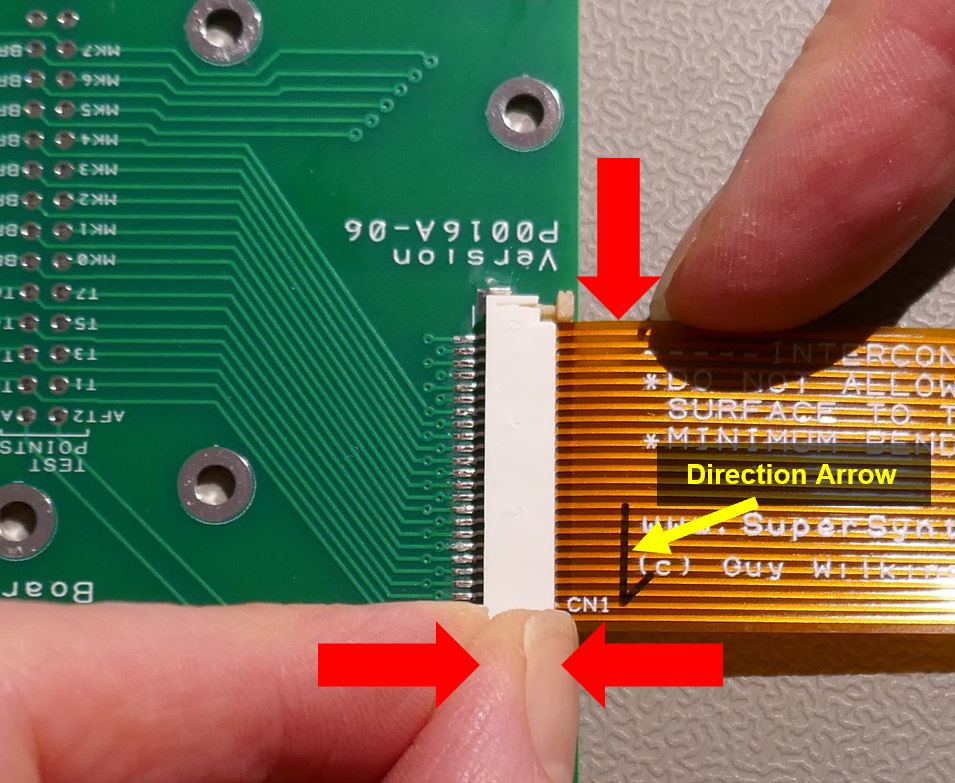
Offset FPC
If you have a flexible PCB with a guide arrow, apply very small pressure, to remove play, in direction of arrow whilst locking the first side at end of arrow. This will assure perfect contact registration. These kits have perfect contacts, are discounted and still guaranteed. Reason is given in the Roland Keyboard Assembly Guide Troubleshooting/FPC Alignment section.
Keyboard Installation
It is now time to install the keyboard assembly into the base unit, taking care not to damage or kink the white flat cable.
Mainboard Connection
At mainboard end, fit exactly as shown with blue stripe facing towards the keyboard.

Testing
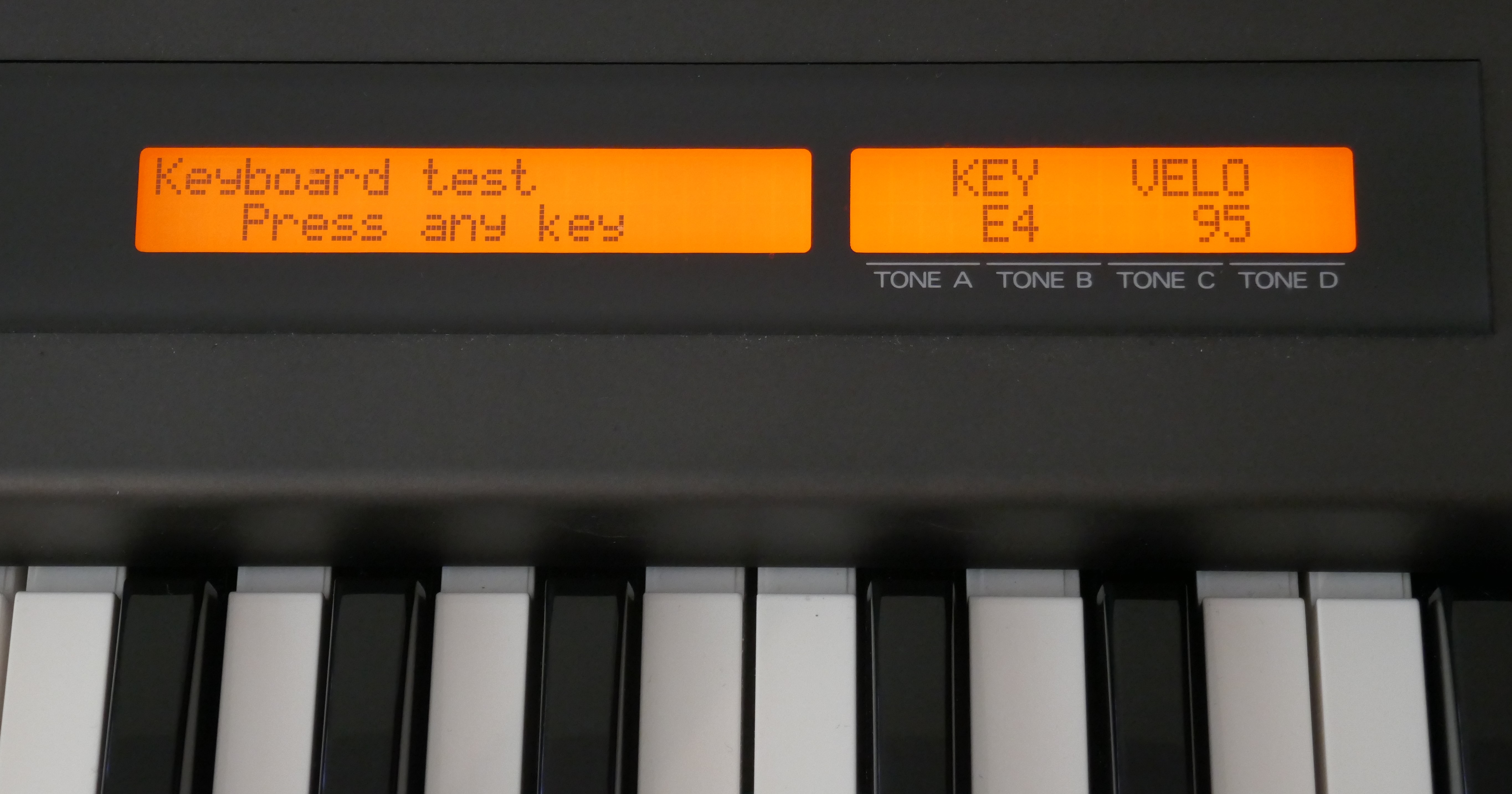
Testing is best performed using the test mode in the synthesizer, it is accessed by simultaneously holding down Cursor Left & Right then pressing Exit whilst Synth is in Multi Mode. Once Test Mode appears, hold Exit and press “NUMBER 3”, keyboard test routine starts and each key can be checked and confirm that velocity is being detected consistently.
Once everything is confirmed, it is a good practice to fully test using a patch that is severely modified in timbre with velocity, such as “Single Mode I-34: Wet Bass”. With this patch, the filter is strongly coupled to the velocity value and therefore gives a very marked variation that helps to discriminate bad contacts caused by contamination. Consistency can be easily checked as you work up and down the keyboard.
The “Fault Finding” and “First Trials” section in Roland Keyboard Assembly Guide shows guidance on fixing faults and ideas to remedy contacts that don’t perform as well as expected. JD-800 specific fault finding is covered below.
Final Reassembly
Once happy, the keyboard assembly should be removed and the plastic strips that hold keys in place are put back into place with double sided tape. The plastic locking strips have shallow teeth that sit in each key hole. In the picture below a flat ended tool is used to push them into place.

Strangely, every keyboard assembly we have seen that has been through a UK tech, has these missing. If not present, the keys will fall out easily!
Secure the keyboard assembly in place and retest before putting the synthesizer back together.
JD-800 Specific Fault Finding
Inconsistent Pickup
The “Fault Finding” and “First Trials” section in Roland Keyboard Assembly Guide shows guidance on fixing faults and ideas to remedy contacts that don’t perform as well as expected.
Not Working
If no keys are detected then a misunderstanding of Type 1 or 2 flexible PCBs has been made or a different orientation of Mainboard white flat cable is present.
When debugging it is important to note that the white flat cable and mating connectors only have electrical contacts on one side. This can lead to a lot of confusion if something is wrong. Type 1 white flat cables have a very clear blue designation line to identify the non-contact side. A picture of the end of the connector below shows a “top contact” arrangement.

Check the contacts between the mainboard and transition PCB test points as per “Keyboard Signals” guide below. It may be necessary to change the position of the connector on the transition PCB but this should be a last resort.
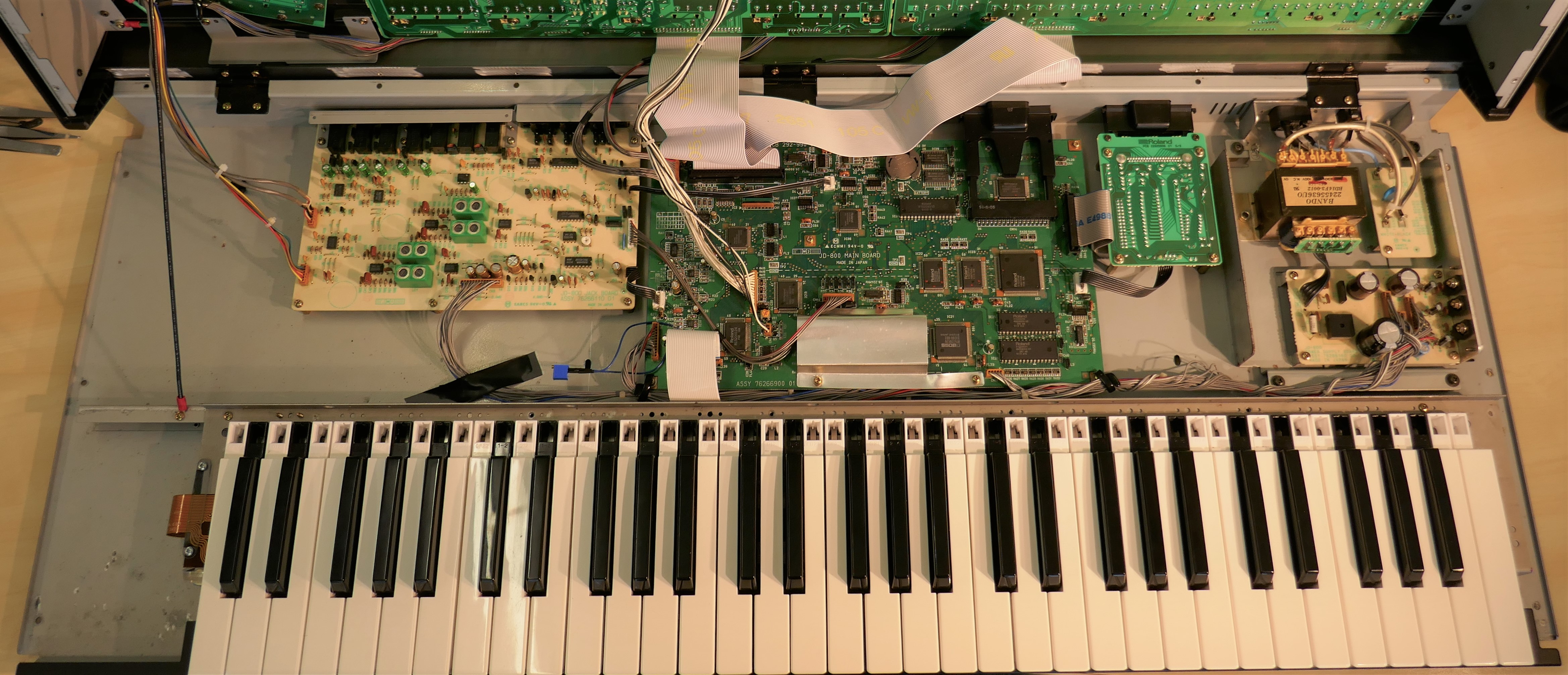
Keyboard Signals
All signals are marked on both Transition board and the flexible circuit, it is straightforward to confirm that these run through to the mainboard correctly. It is important to get the mainboard connection correct as it can connect to either side of the flexible circuit and if wrong will reverse the signals. One side of the contact is designed to clamp the plastic backing and the other is a contact point, it is therefore essential to get orientation of the flexible circuit correct for reliability.
The picture below summarises pages 13, 17 & 18 of the service manual that show how it is connected up.
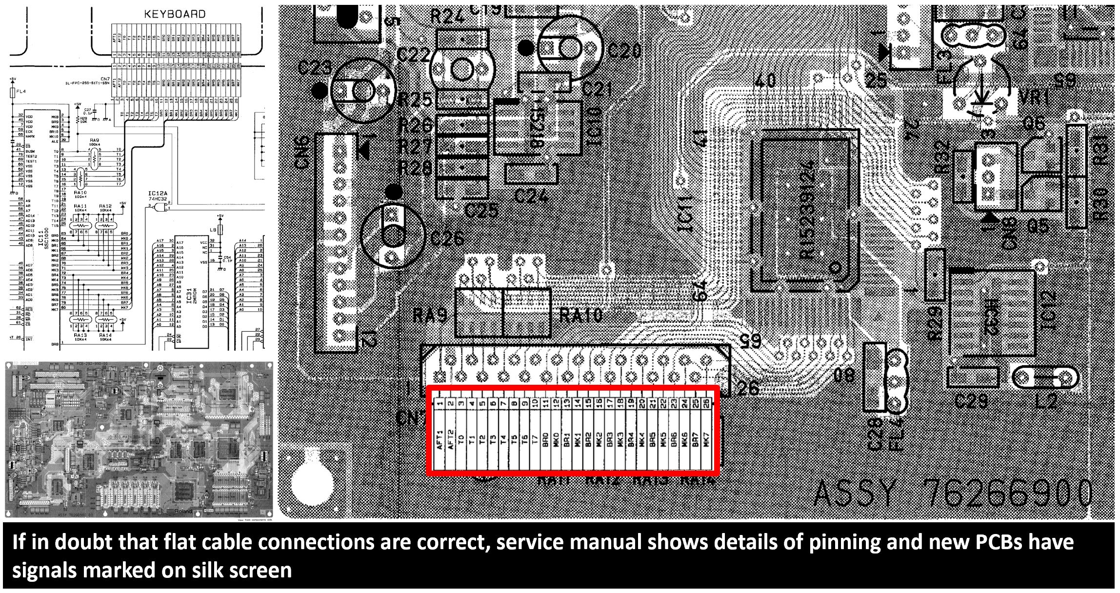
See the Troubleshooting section inside the Roland Keyboard Assembly Guide.
Aftertouch
The new PCB kit does not fix issues with the Aftertouch (AT) connector, however the potential areas are covered below if you desire to get it working again.
Connector Issue
Usually, cleaning connector contact areas with IPA is all that is needed to get this back to life.
The end of the sensor has contact points that are made of carbon and mate with nickel plated connector can become more resistive with time. The AT sensor is only a resistive type and can pass current in either direction so connection orientation does not matter.
One user has reported that twisting the AT flexible connector 180 degrees before insertion fixes this issue as it utilises fresh / correct contact areas. Some contact areas are only present on one side too. Maybe the user had installed the Aftertouch connector on the wrong side of the transition PCB.
In extreme situations, it is possible to rejuvenate this by rubbing graphite powder onto the carbon contact areas.
An important note is that when unplugging the AT connection, the adhesive tape used by Roland is very sticky and the adhesive can touch the end and contaminate it. Cleaning is therefore often necessary.
Aftertouch Performance
The kit doesn’t fix the Aftertouch sensor performance, that can be difficult. On JD-800 Center, there is a modification described. The components used in the fixed resistor type are too big for attaching to SMD pads safely. Go to bottom of the page of the modification page for a nice solution using a potentiometer and wires. Ideally a miniature multi-turn trim potentiometer and 30 AWG wire of the type used in wire wrapping prototyping should be used.
Here is our version of the Aftertouch Modification in our instrument using 30 AWG wire, a Bourns 12 turn 500K trimmer potentiometer 3266W-1-504LF glued to the motherboard PCB and connected across R27. When glueing, take care not to get any on the adjustment screw.
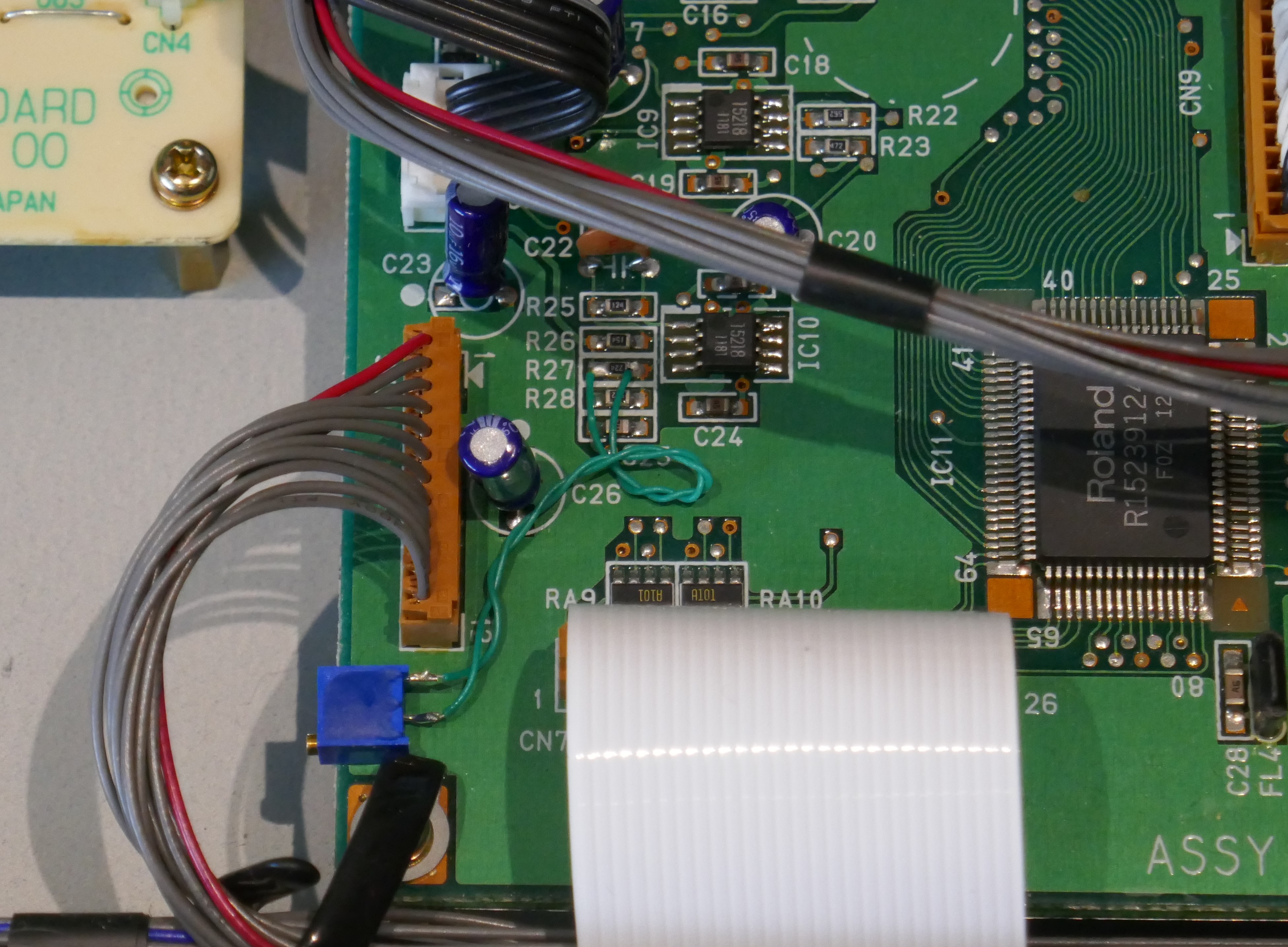
Note that we had to clean the Aftertouch connector contacts with IPA otherwise it wouldn’t give any reading at all. Using a multimeter on resistance range, we also noticed open circuit even when keys were pressed hard. The socket was cleaned using a piece of card slightly wetted in IPA. This shows that some issues can be with the connector arrangement, not necessarily with adjustment or sensor itself.
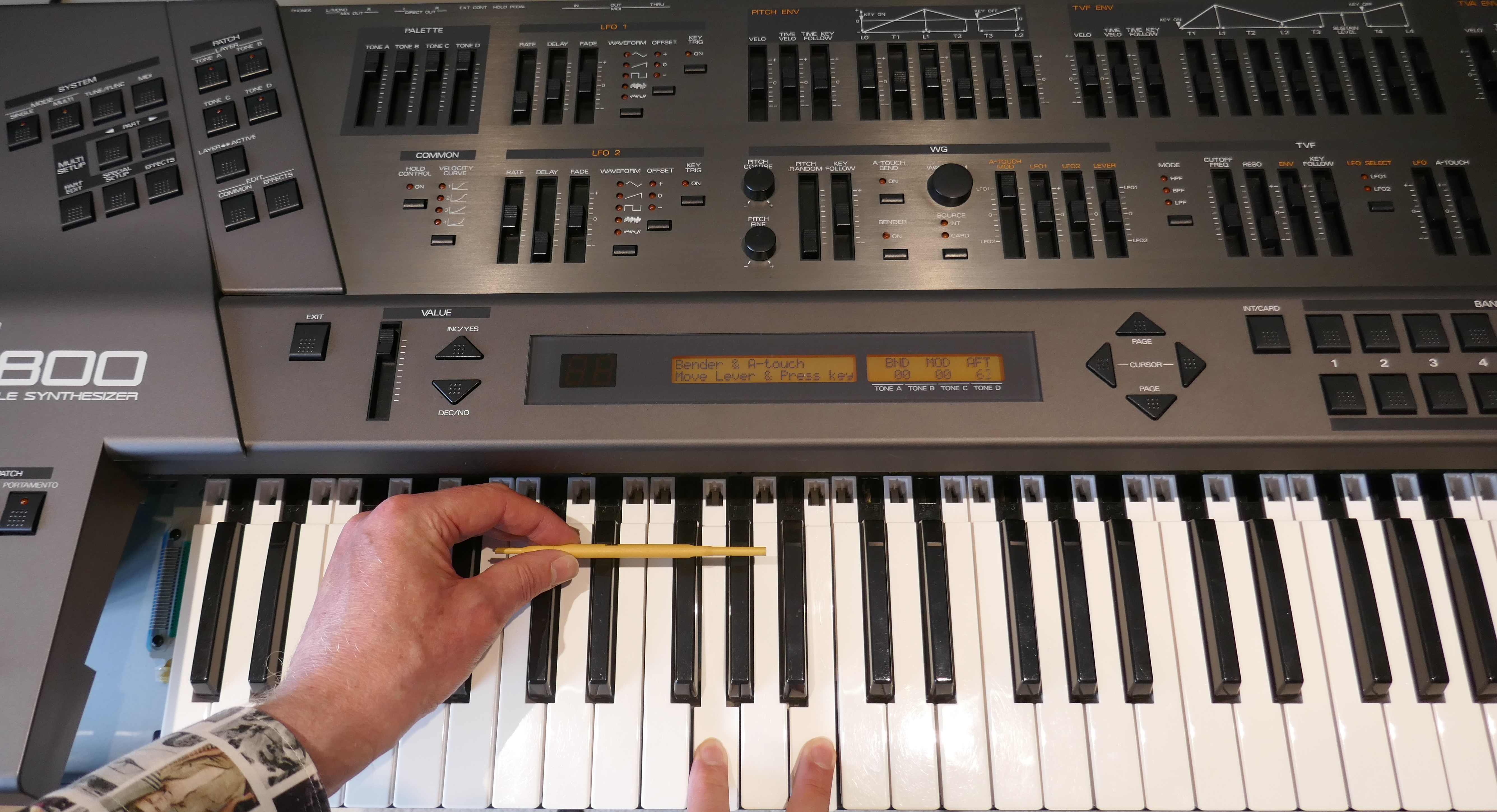
Adjustment is using a trimming tool and the lid propped up just enough to allow adjustment.
Testing is best first performed using the test mode in the synthesizer, it is accessed by simultaneously holding down Cursor Left & Right then pressing Exit whilst Synth is in Multi Mode. Once Test Mode appears, hold Exit and press “NUMBER 1”, Aftertouch, modulation and bender test routine starts.
Adjust the sensitivity on the potentiometer to taste by pressing a key and observing the aftertouch value, the maximum value is 127. Trial with a number of keys pressed together too.
Once done, exit test mode by simultaneously holding down Cursor Left & Right then pressing Exit. Test a patch such as “Classic Sweeper” for sensitivity, re-adjust if necessary.
In this particular instrument, the keyboard had been rarely played since the mid 90’s and suffered from red glue on the aftertouch sensor; resulting in poor performance. Sensitivity adjustment on this instrument essentially makes the behaviour of the sensor more like a switch (unlike our U-20 that we modified in same way). If other users report similar, we will do another article showing how to circumvent this issue.
Copyright © 2021 Super Synth Projects, Guy Wilkinson & Jonathan Williams

You must be logged in to post a comment.