

Using my JX10 was frustrating when playing it because the keys were strangely unresponsive or dead in places. An attempt was made to fix the issue using conductive paint, however I received a “tip off” from a JX10 user in France that there was a Roland key contact part available for another instrument that will fit!
First Attempt – Conductive Paint
First attempt was to resurrect the old membrane contacts using purpose made conductive paint.
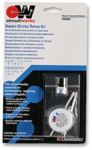
“CircuitWorks” membrane keypad repair kit was used with little success on the JX10, two keys failed after around a year with the rest of them being less responsive: a kind of “delayed reaction”. CircuitWorks kit has been successful in the past, managing to rescue a couple of ancient synths that don’t have velocity sensitivity.
The reason for failure on JX10 was my fault, I didn’t understand the science at the time. A full examination of tests on contacts is examined in the JD-800 keyboard failure modes.
Adding metal or highly conductive surface to the top contact generates a complex random digital pulse train, known as switch bounce, overriding the hysteresis function and confusing the keyboard scan chip during velocity measurement.
For velocity sensitive keyboards, using conductive paint to restore contacts doesn’t work on the top contact, it must be applied to the bottom carbon contact and the top rubber contact cleaned thoroughly instead.
The coating also makes the surface less flexible such that particles of dust cause the contact to not engage, in a keyboard, the pressure put on the contact is very low, unlike a typical user interface on a pocket calculator.
The CircuitWorks kit is shown below, only use it if you can’t get replacement contacts for your synth and remember that once done, it can’t be undone. Also expect to be popping open the keyboard again in the future, to give everything a clean or repaint.
Second Attempt – Substitute Roland Part
This part is for another instrument and is still current production at Roland but fits the JX10! The Roland Part number for the 12 way strip is 2218523802 and 7 are needed. It has been confirmed that these parts come from the Roland EP 760. They may also be in the VA3 VA5 VA7 instruments too. Thanks to Alun Harrison for this information.
The picture below is proof that it is an original part sourced in the UK.
In USA, a possible source for these parts is Full Compass
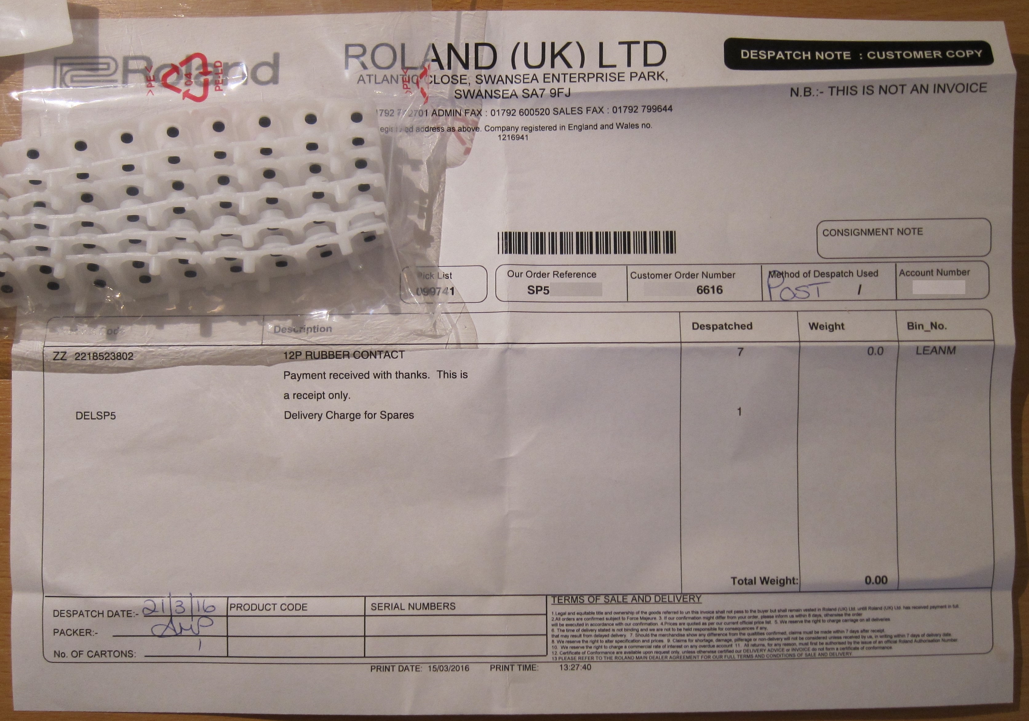
The 7 rubber strips cost 35GBP including postage within the UK and arrived within a week.
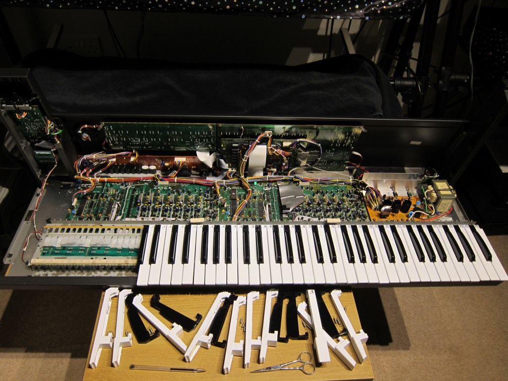
Tools & Materials
- Crosshead screwdrivers – to open the JX10
- Ruler – to hold down the dust protection strips
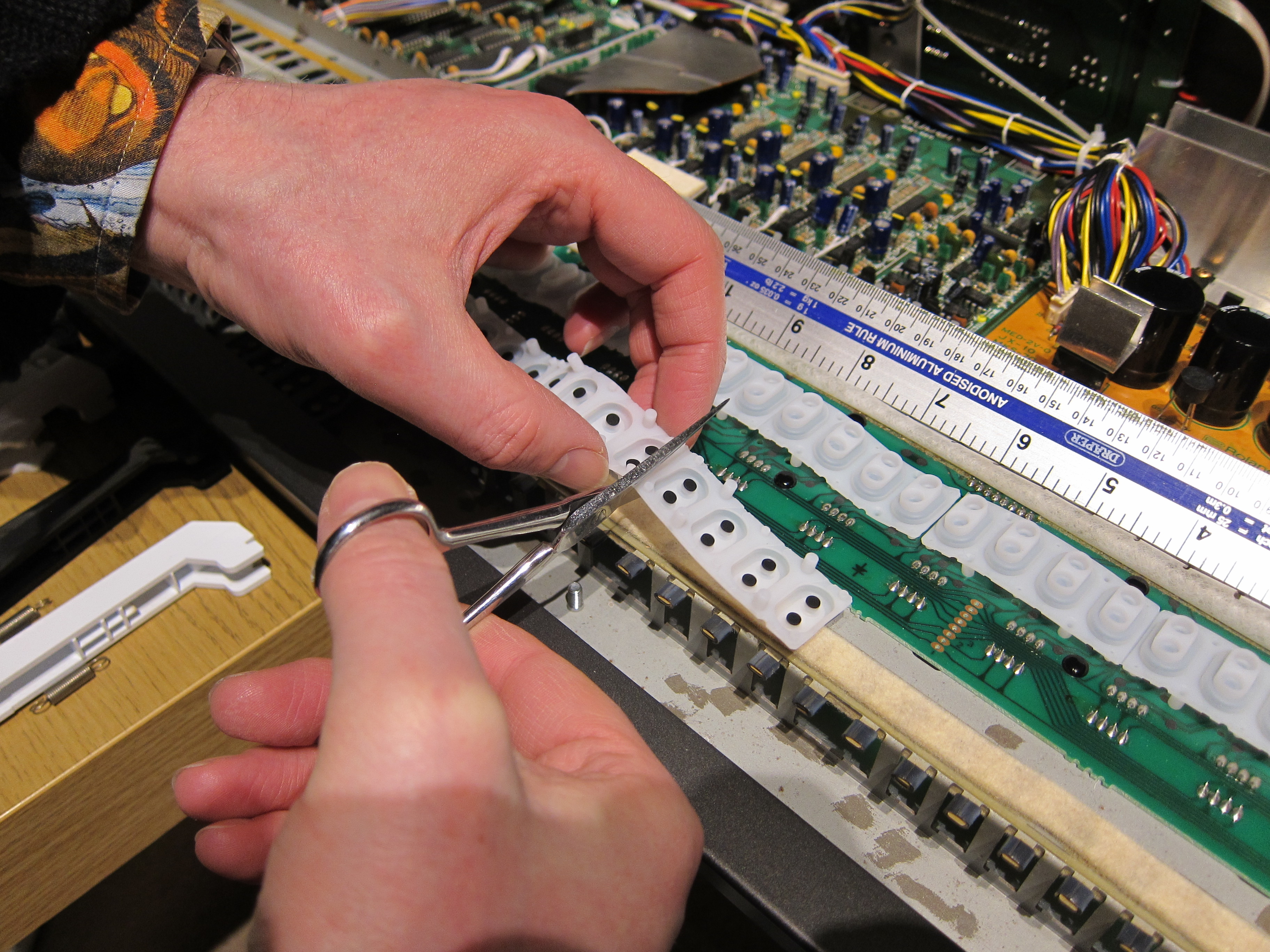
- Scissors – to trim the final membrane to length
- Tweezers – to remove and fit 4 springs around two front panel supports.
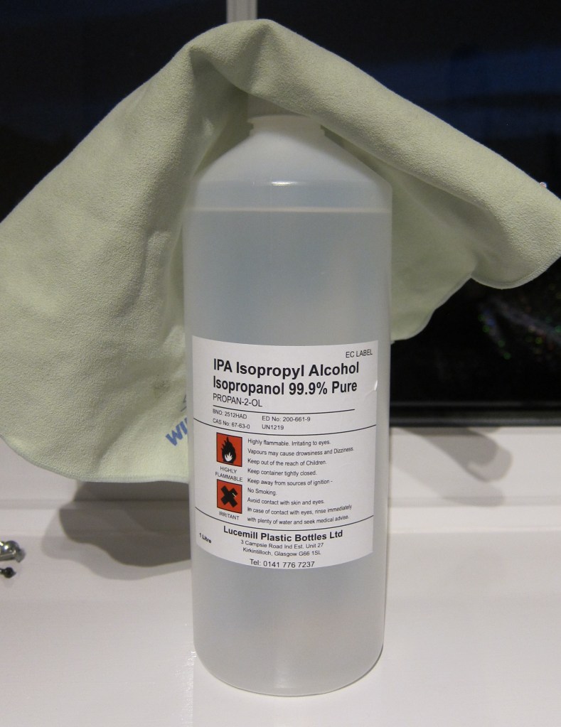
- Isopropyl Alcohol & Clean Cloth – clean the carbon contacts on the PCBs
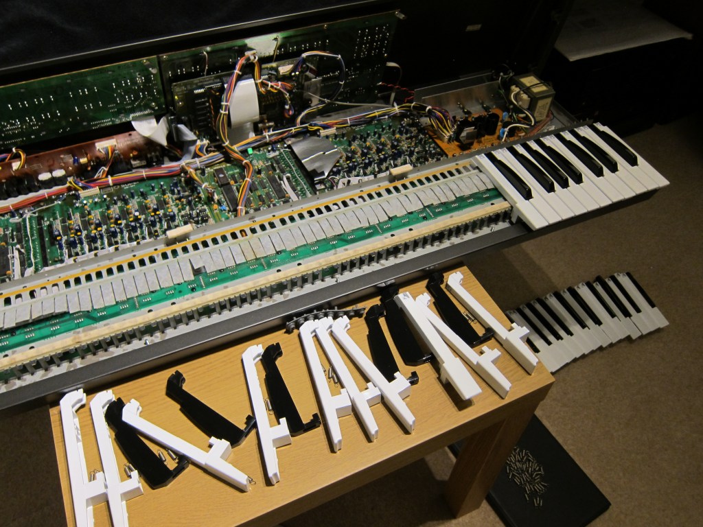
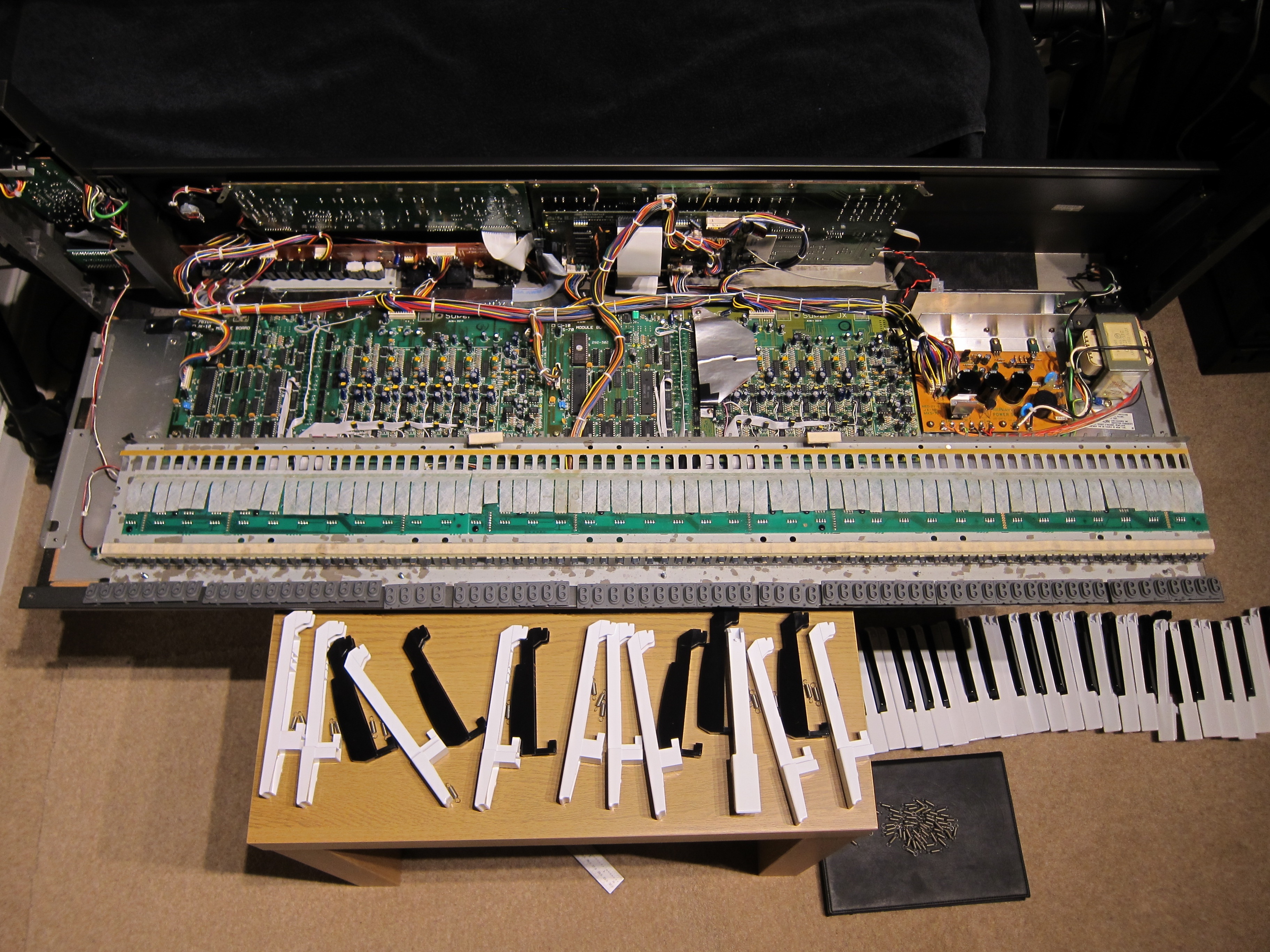
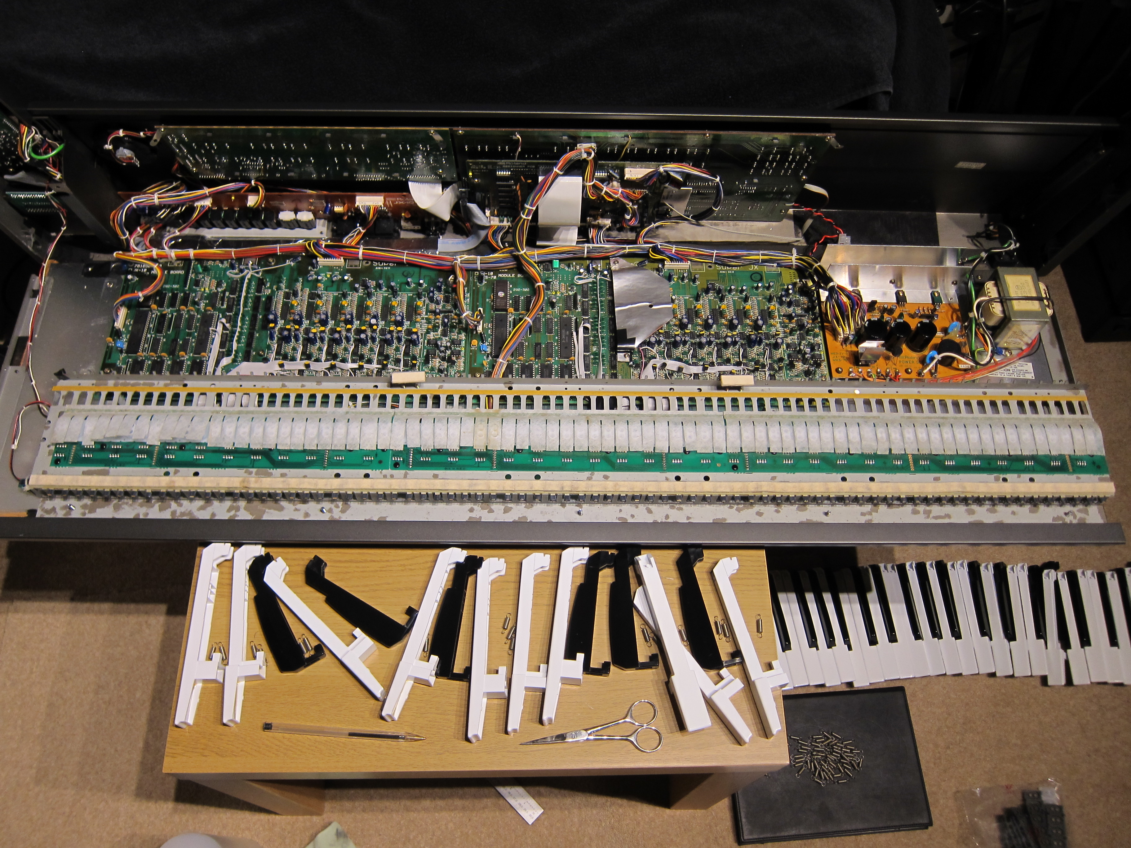
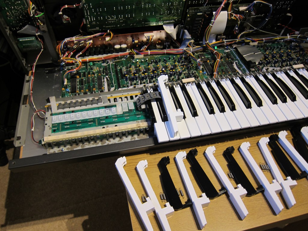
Remove the Springs & Keys
It is best to remove all springs first, followed by the keys.
Pinch the springs firmly with fingers and unhook them at the metal support.
The first few white keys on the left are held in place with a small piece of clear plastic situated underneath the metalwork, just push this down a millimeter or so then pull on the white key to release it.
White keys lift out after being pulled forward and moved to the side.
Black Keys require the neighbouring white key to be pulled forward a little.
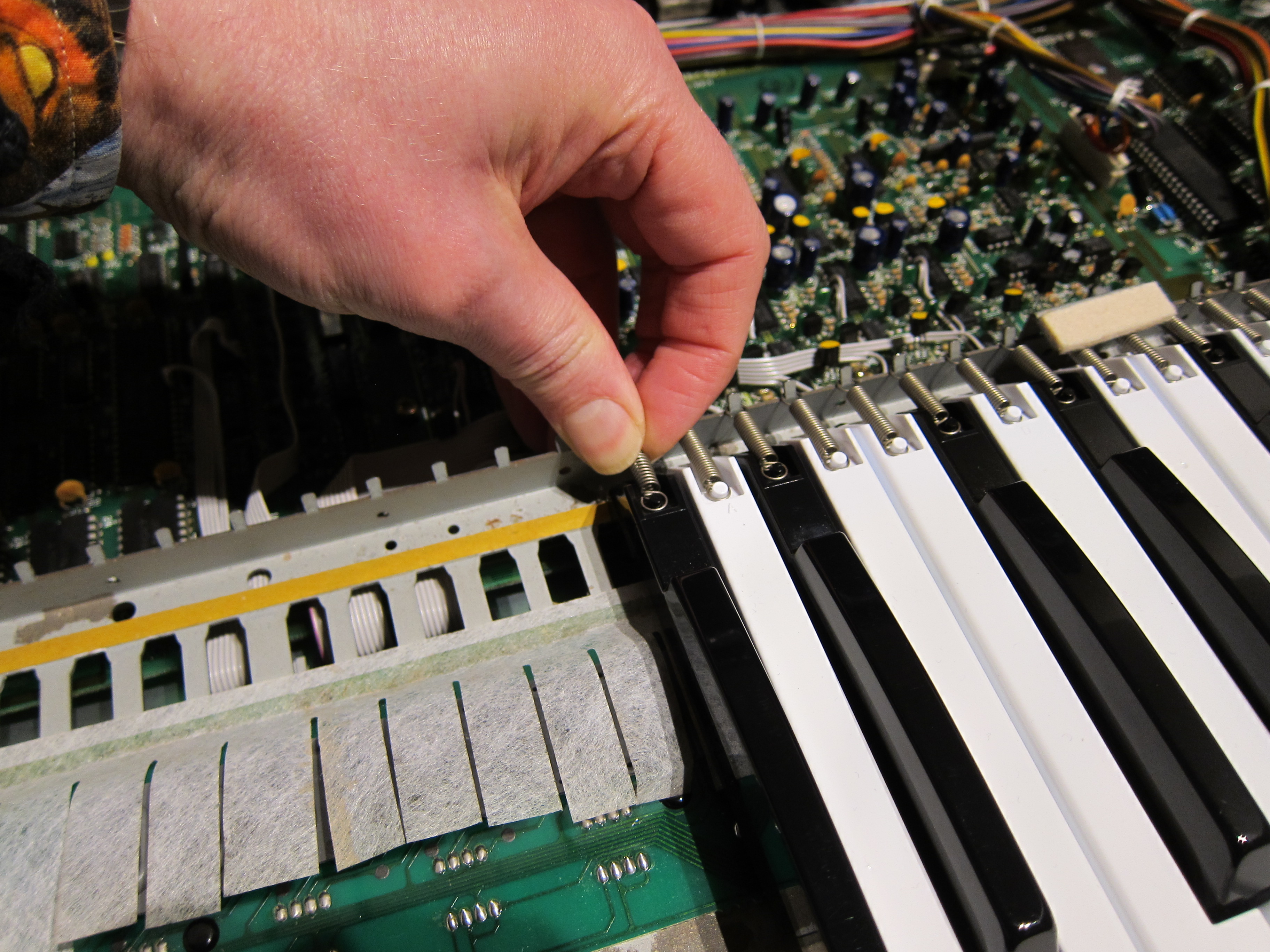
Near the front panel supports, the springs can be removed with tweezers, but be wary of them pinging out and disappearing somewhere! A spring lost within the circuit board could be tragic.
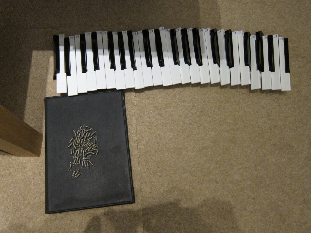
Gradually remove all keys laying them down in order so that it is quick to put them back. In my case, I cleaned and polished the keys with T-Cut and vacuumed the PCB and metalwork to remove all traces of dust.
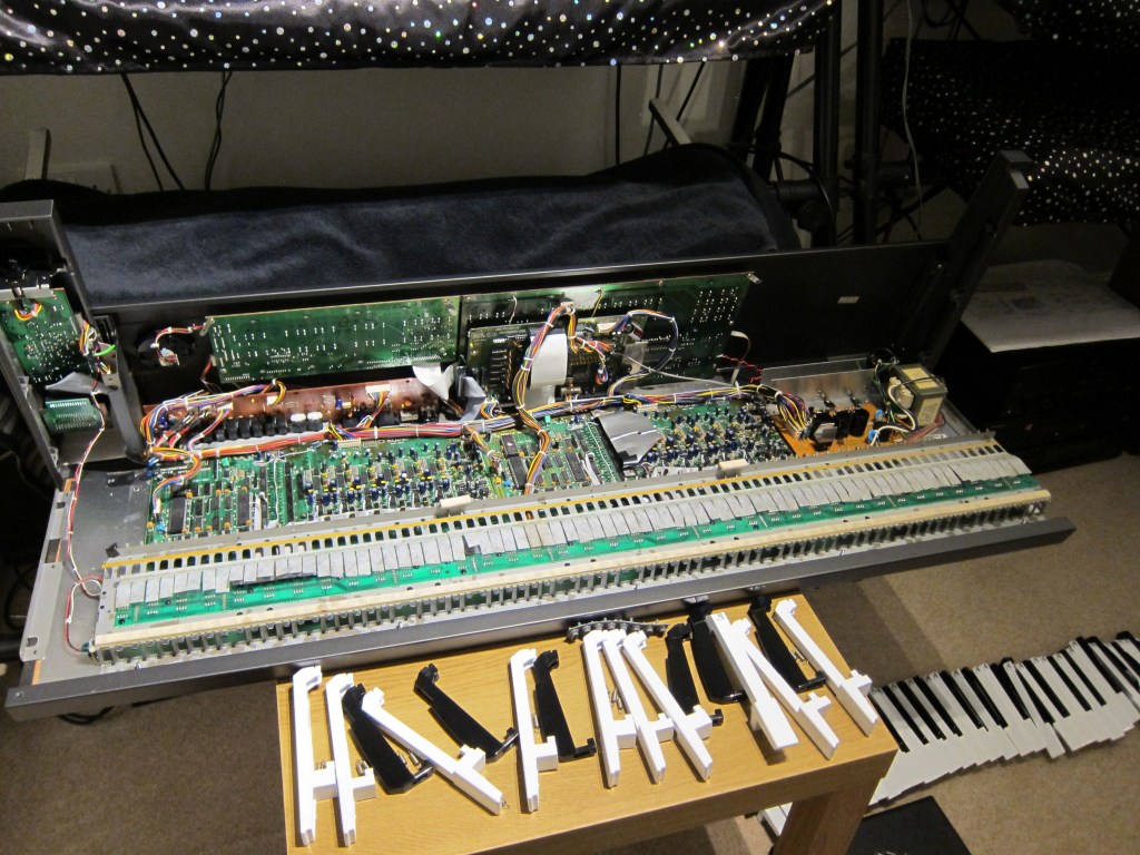
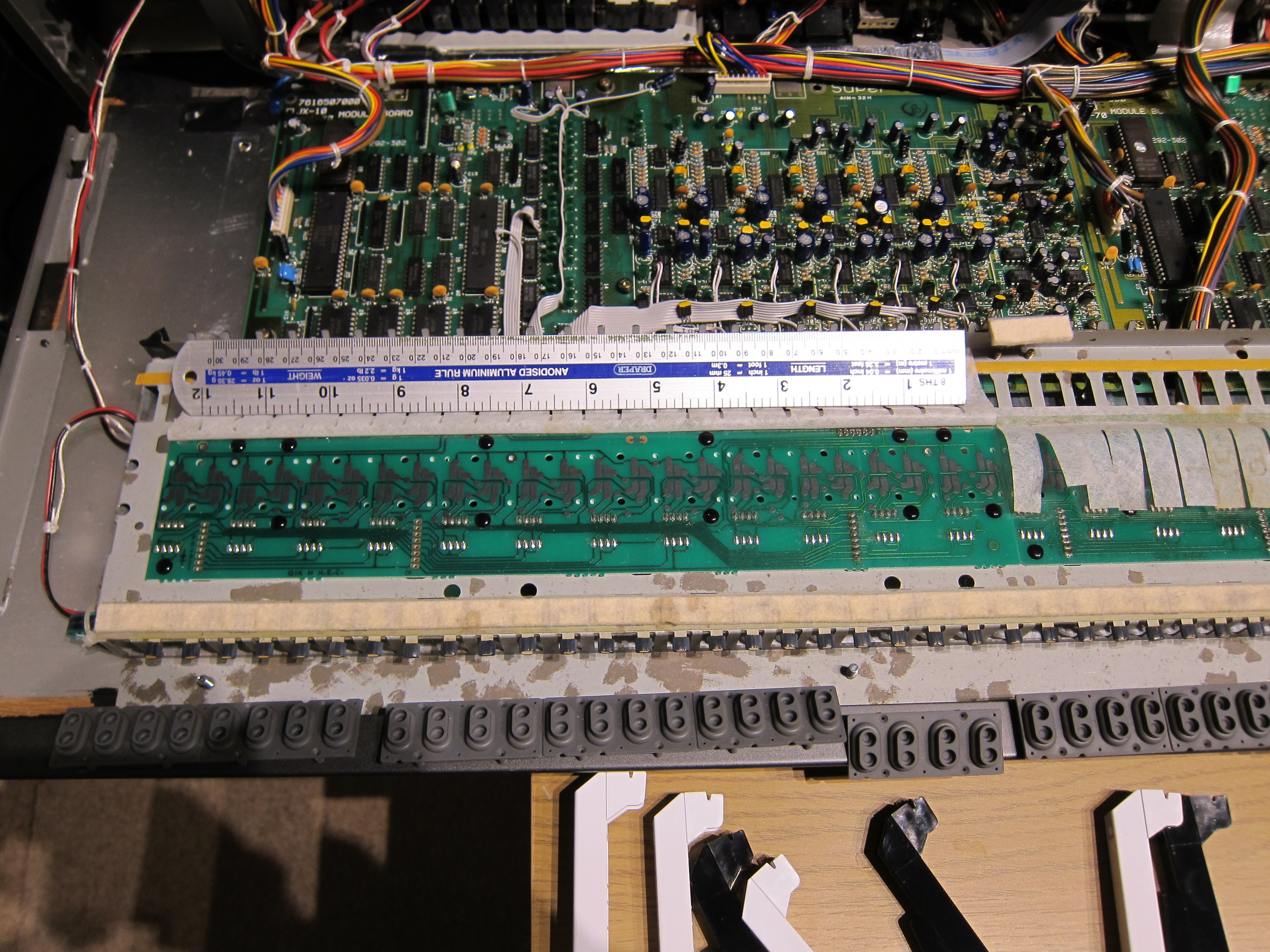
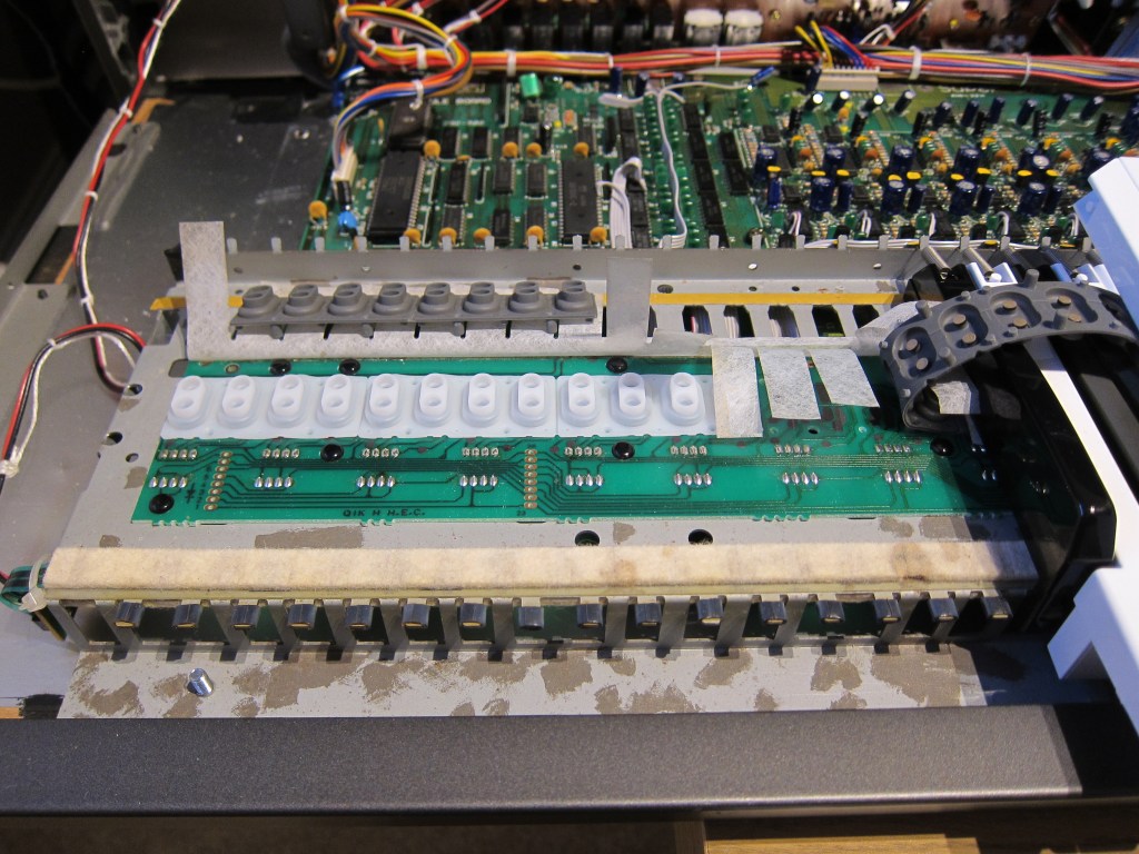
Membrane Contact Removal
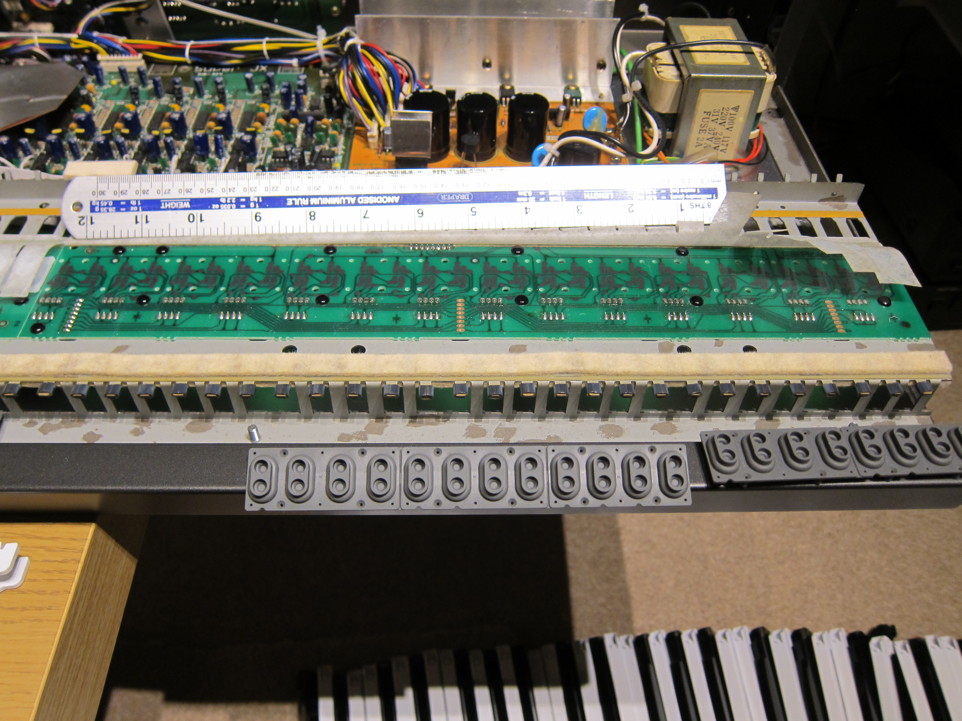
Simply pull these out, they may be worth keeping for the future. In the picture below, you may notice blemishes on the metalwork, this is where rust has been treated.
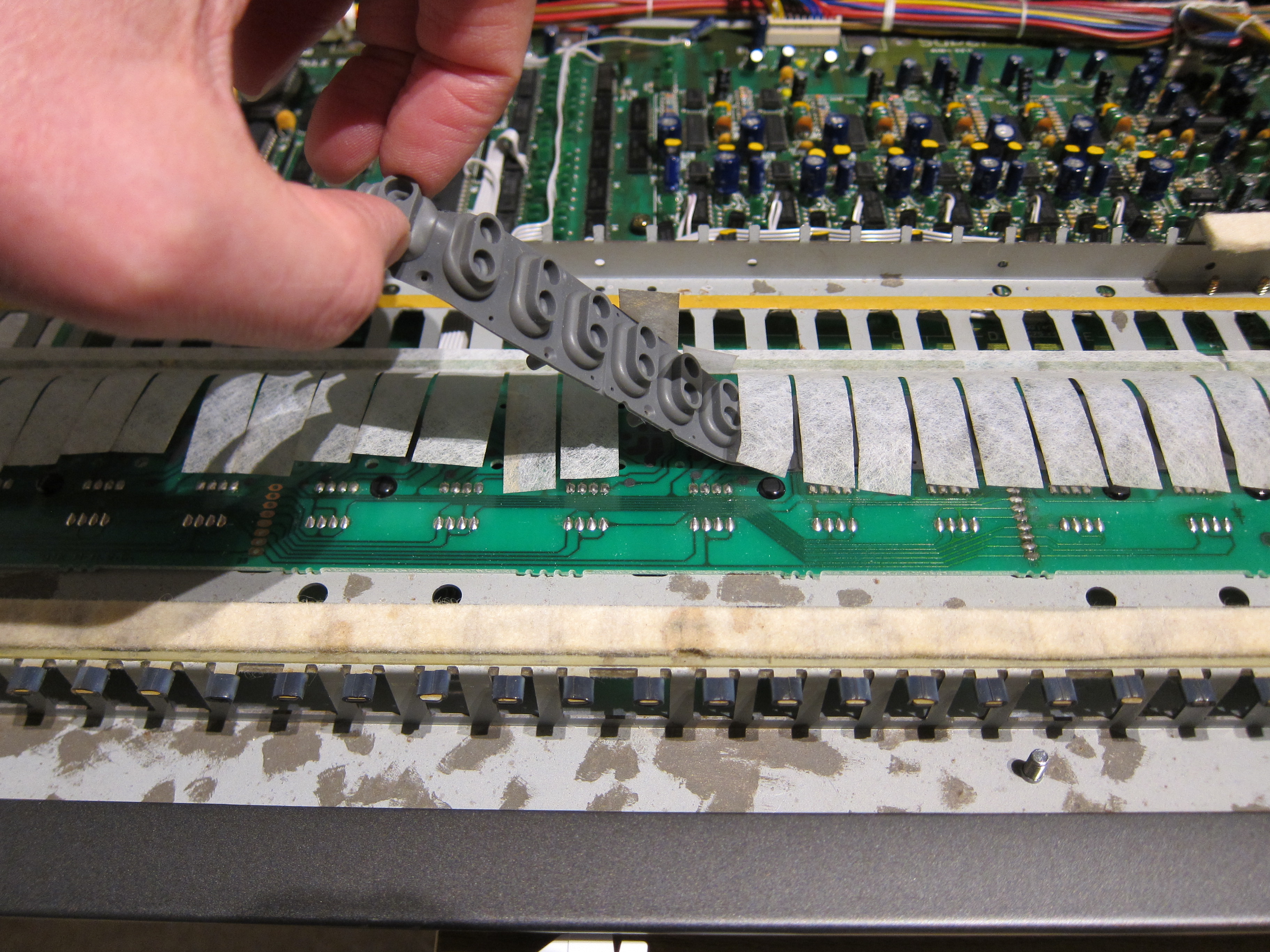
Membrane Contact Fitting
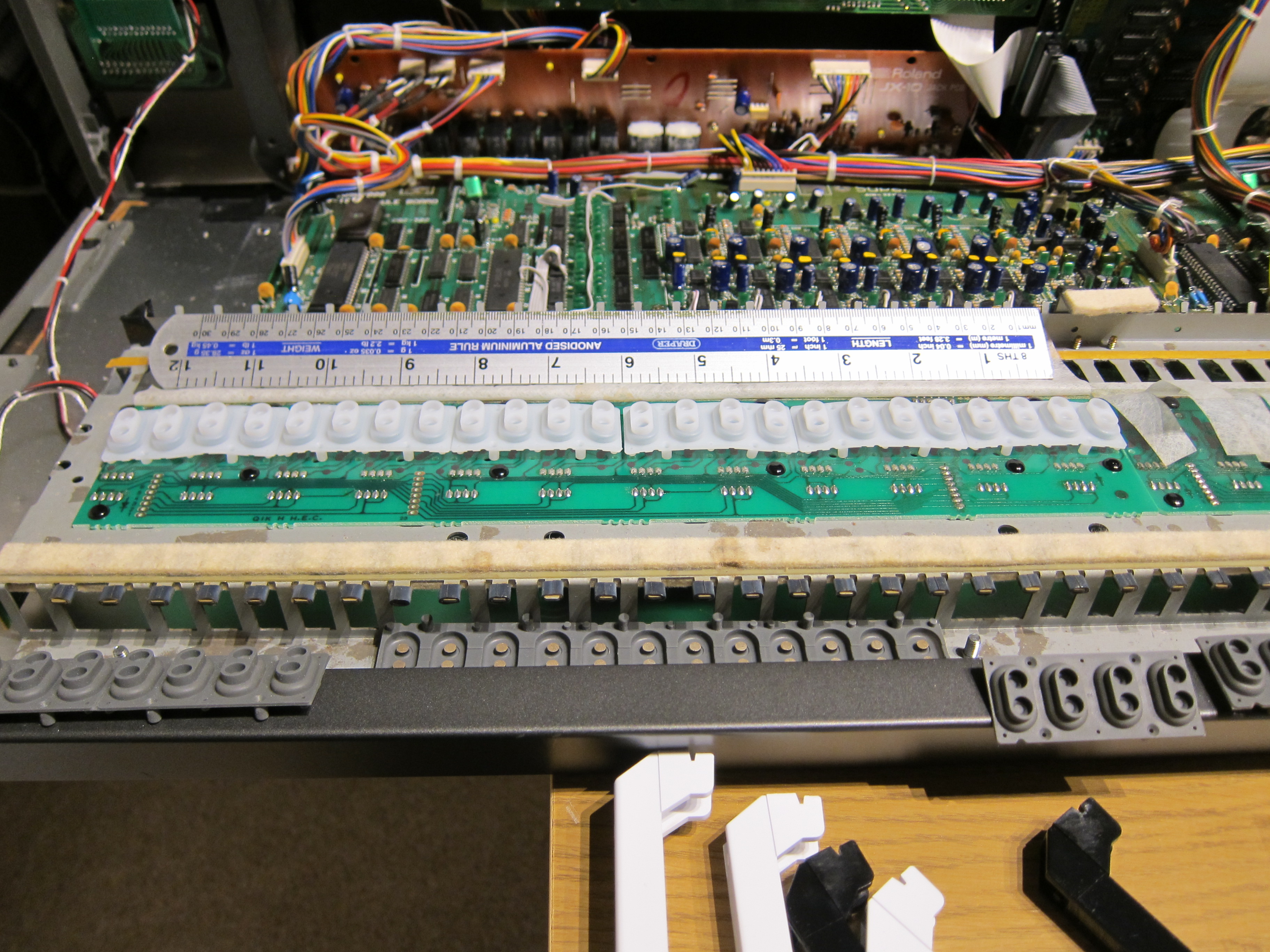
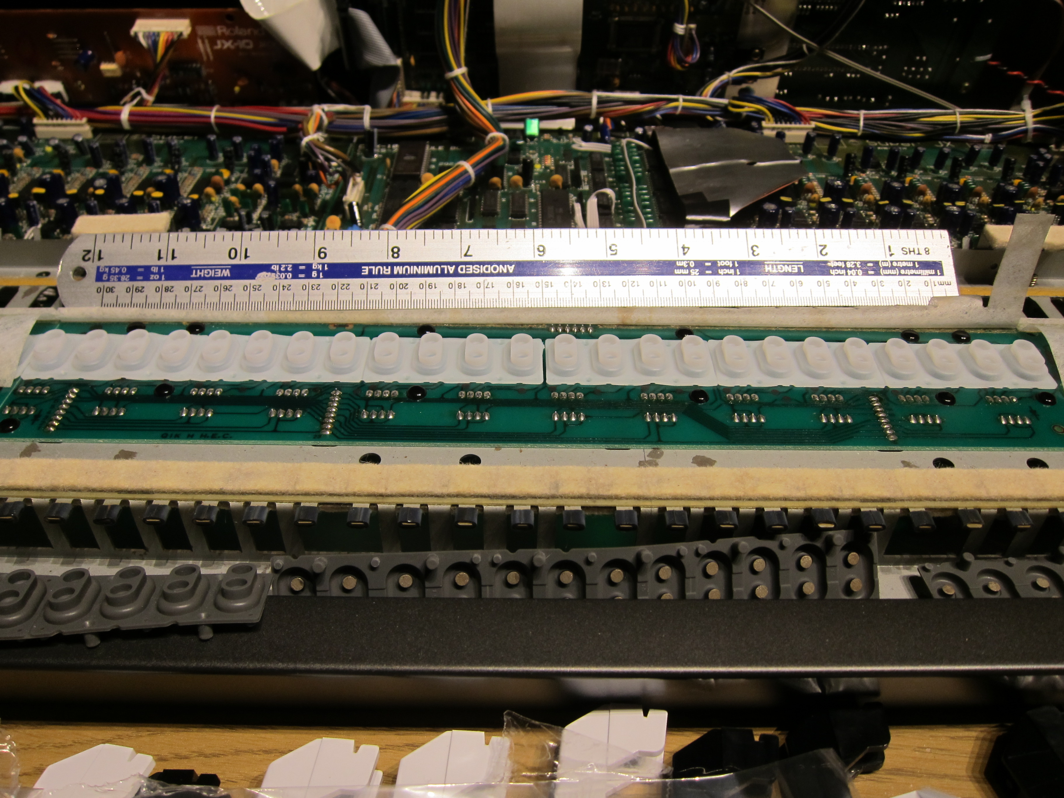
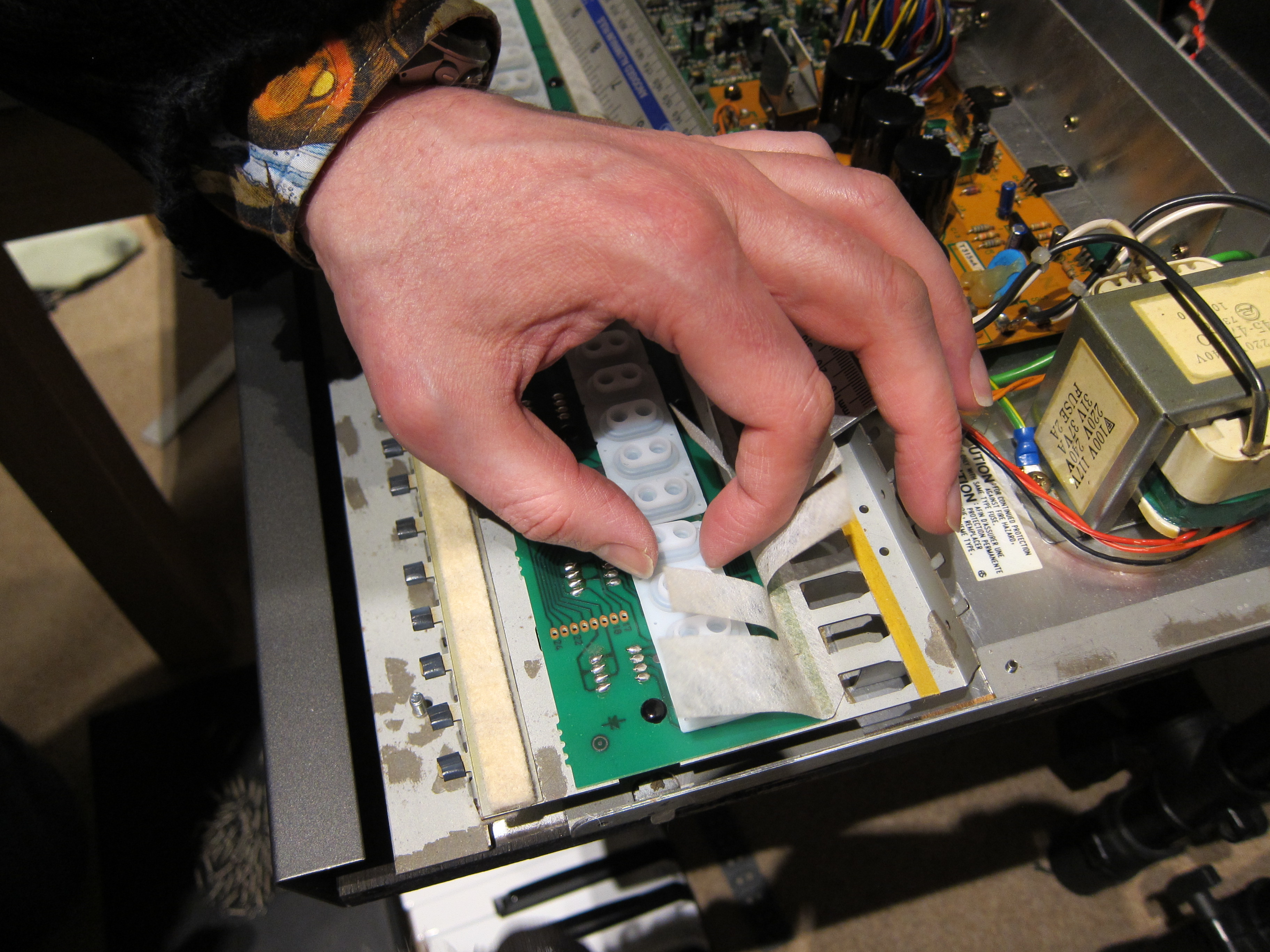
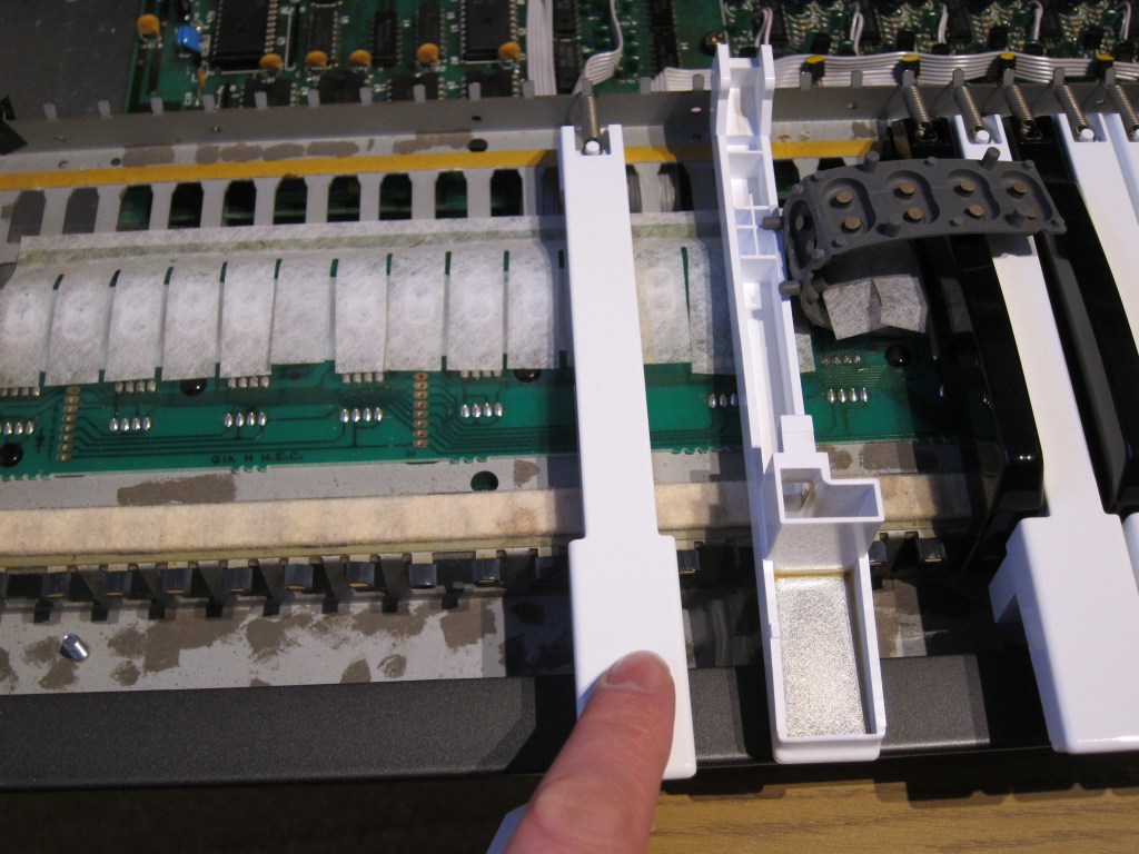
Carefully push a ruler under the dust protection strips. The main purpose of the dust protection strips is to reduce friction between the key and the rubber contact. Be wary of removing them completely, they are needed for making sure the rubber membrane stays in place when the key strikes.
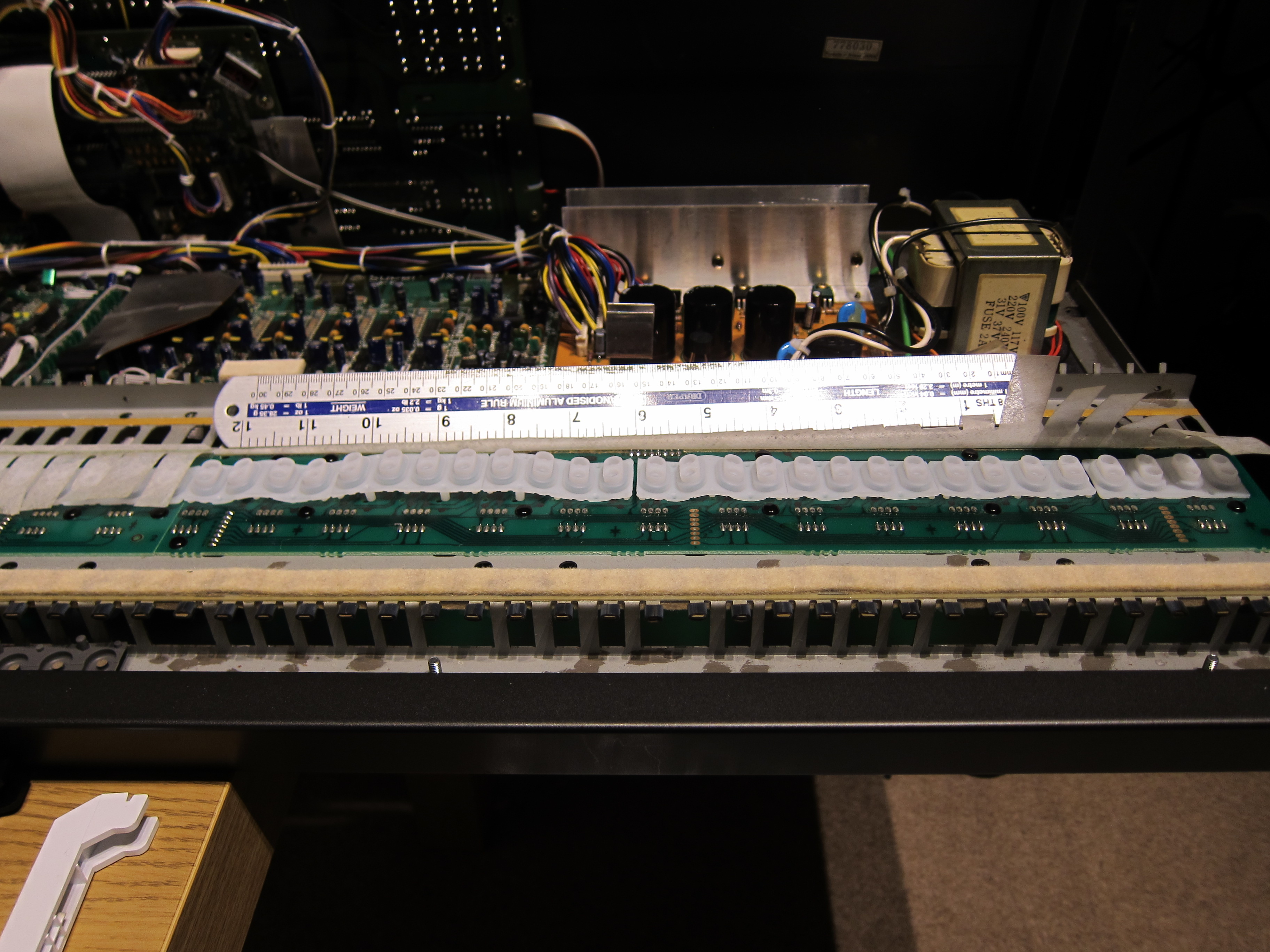
This next section is done one PCB at a time, that are conveniently one foot long.
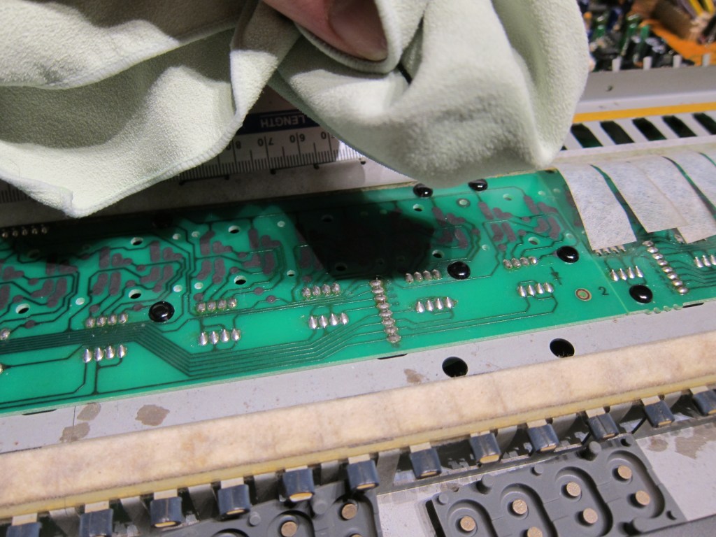
Cleaning
Use IPA to remove any dirt. This must be done with just one or two “rubs” and a dry run with the cloth immediately afterwards to remove any possibility of residue. Do not scrub the carbon on the PCB, it rubs off very easily and you only need to remove dirt build up.
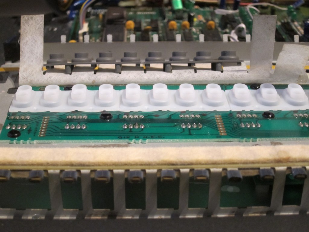
Membrane Placement
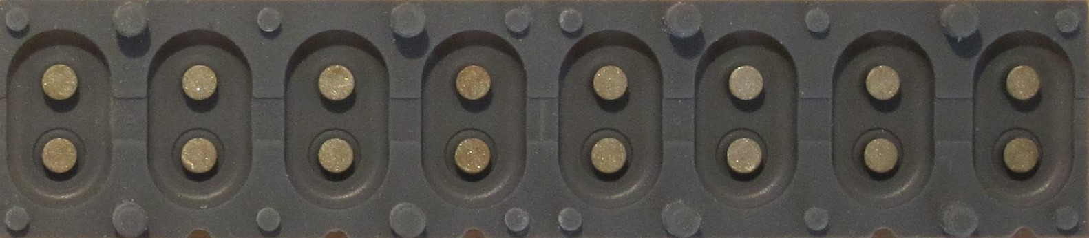
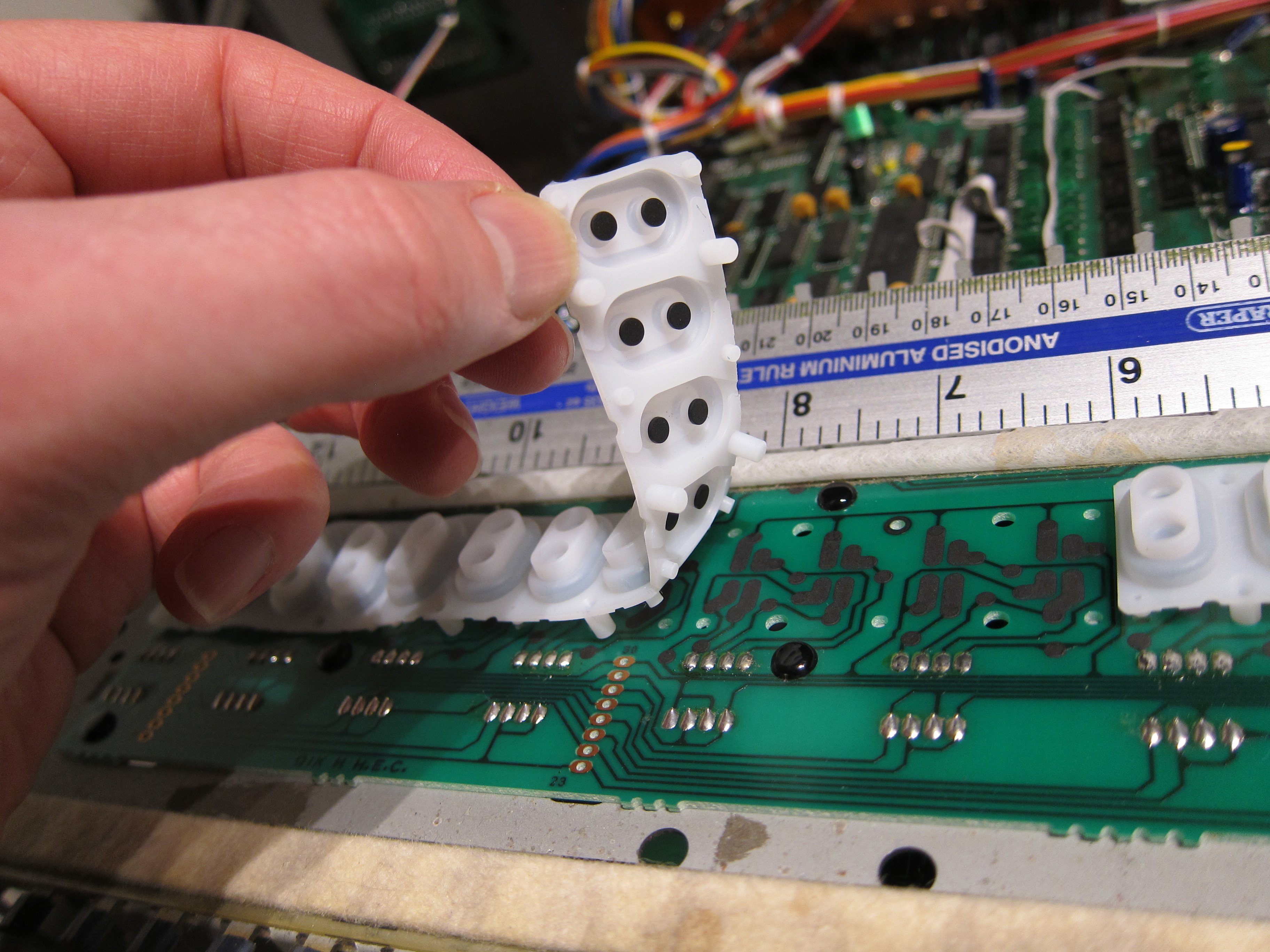
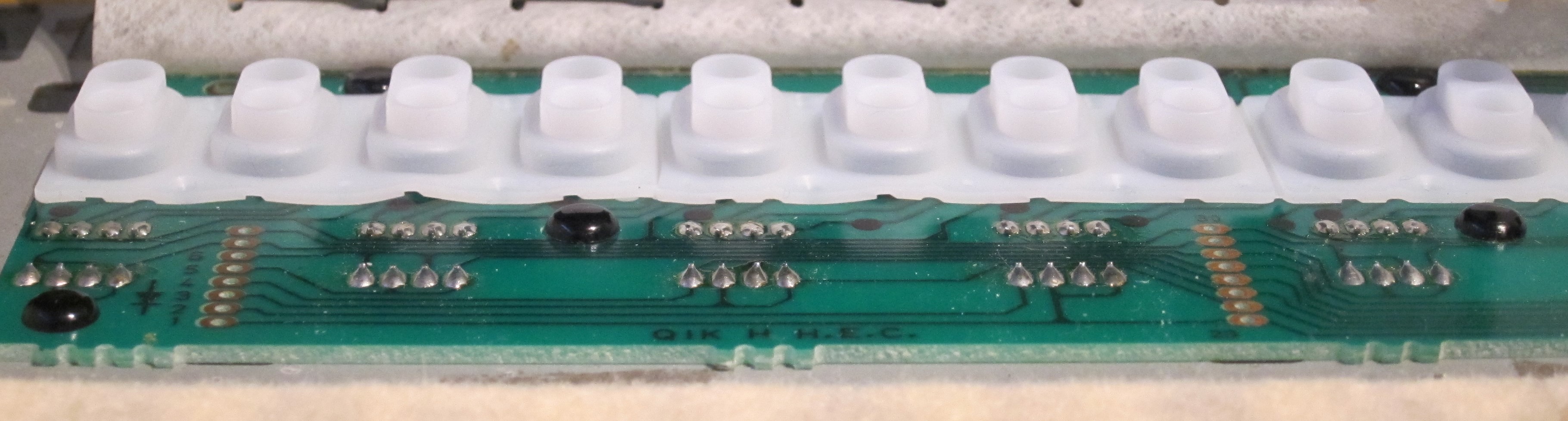
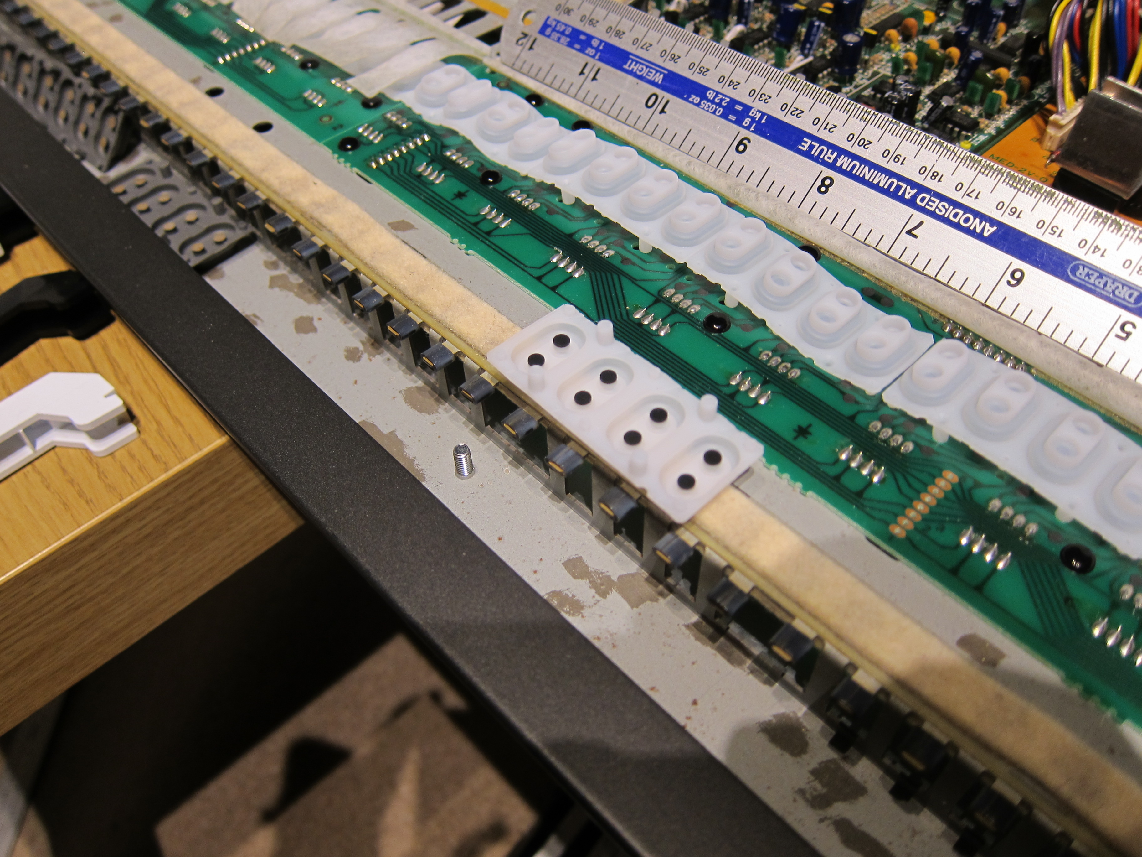
Avoid touching the contacts on the PCB or membrane with fingers to avoid any kind of contamination. Make sure that dust on the PCB is removed then lay the contacts in place. Positioning is vital for the velocity sensitivity to work, the membrane has small “nicks” along one edge, point these towards the front of the keyboard.
As can be seen below, the longest “pip” in the membrane is towards the rear.
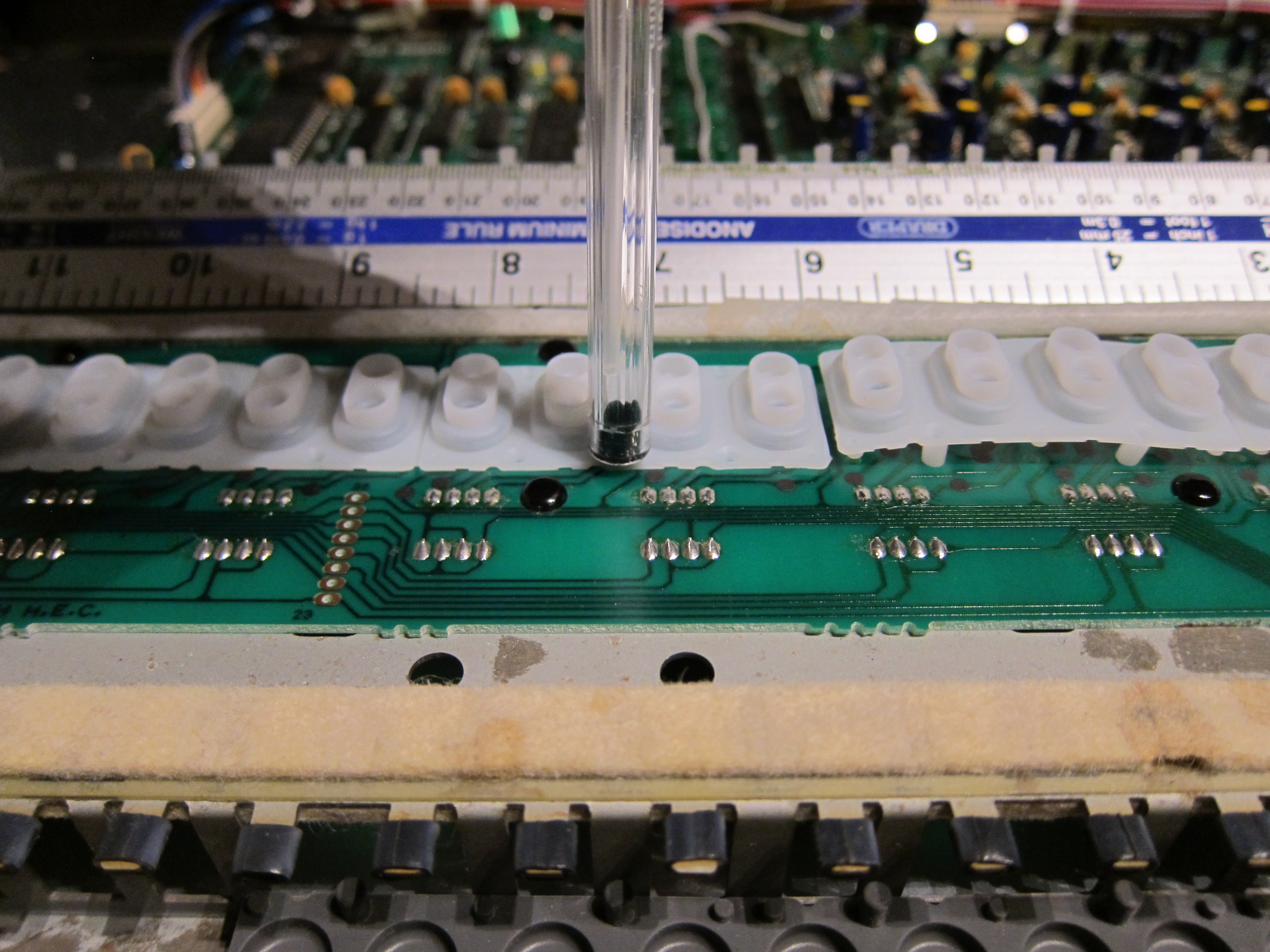
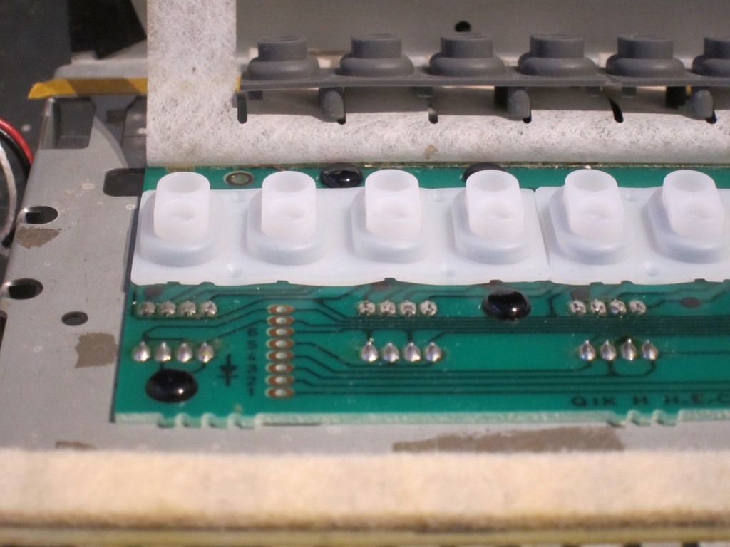
First, engage the long protrusions into the large PCB holes, do this for two strips on one PCB at a time.
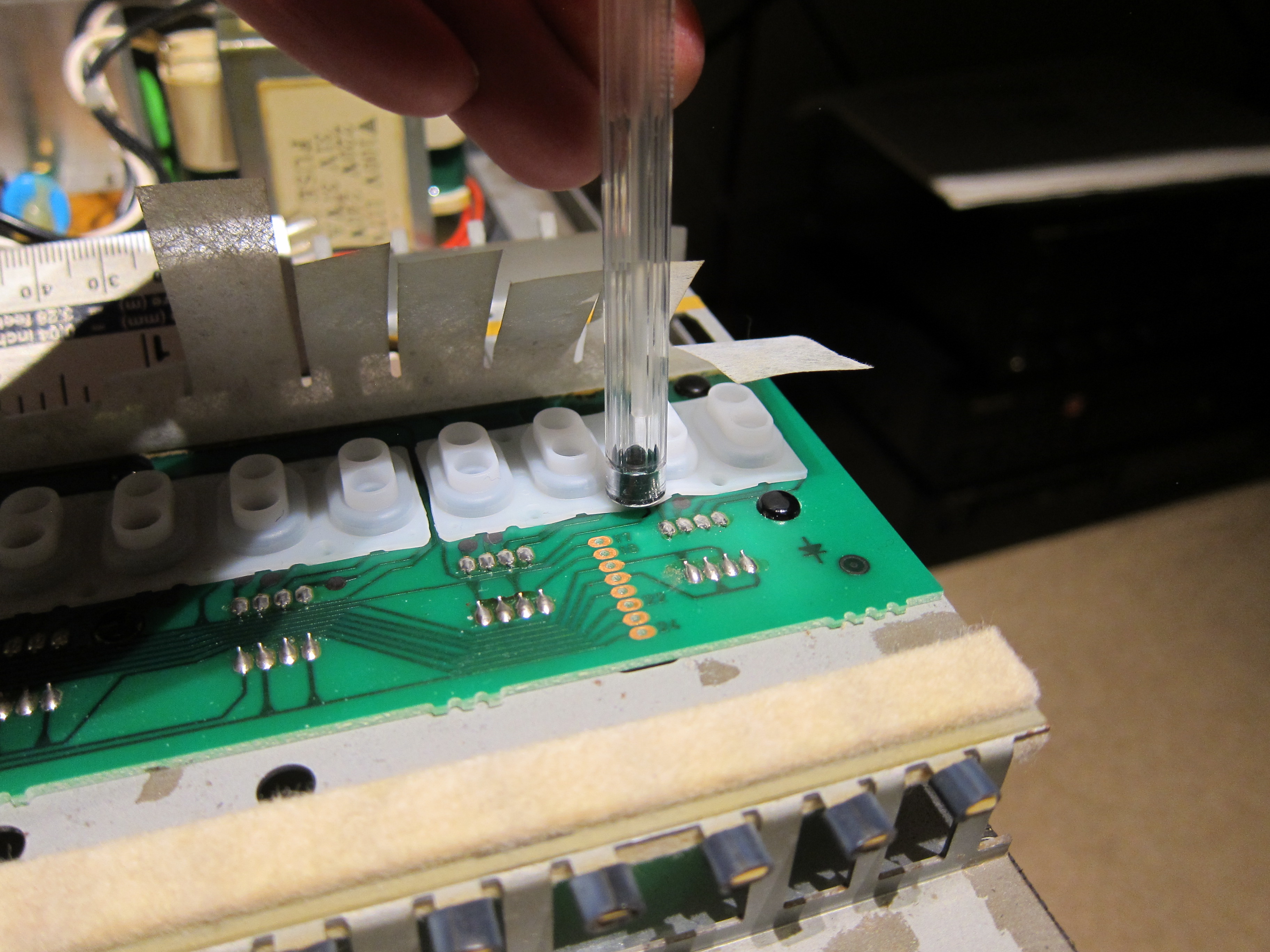
Second, press the short protrusions into the PCB holes ensuring that they bed in tightly. It is a good idea to use the back of a BIC pen rather than a fingernail as it exerts even pressure and seems to pop in more easily.
One they are all in, press all protrusions down again to make sure that they are fully bedded in.
Because these new membranes are not specifically for the JX10, they will “ruck up” a little. This in practice doesn’t seem to matter or affect the response.
Time will tell if this actually is the case, but after quite some time everything still works perfectly. See later section for more comparison pictures.

Start the next PCB in the middle of the keyboard and repeat the same process:
- Clean
- Place two strips
- Press long protrusions in place
- Press short protrusions in place
- Press all protrusions again to make sure membrane is flat
Finally the last PCB on the right of the keyboard, there are 16 contacts on this one.
Trim one membrane down to 4 contacts and put in place.
Same process for fitting as all the others….
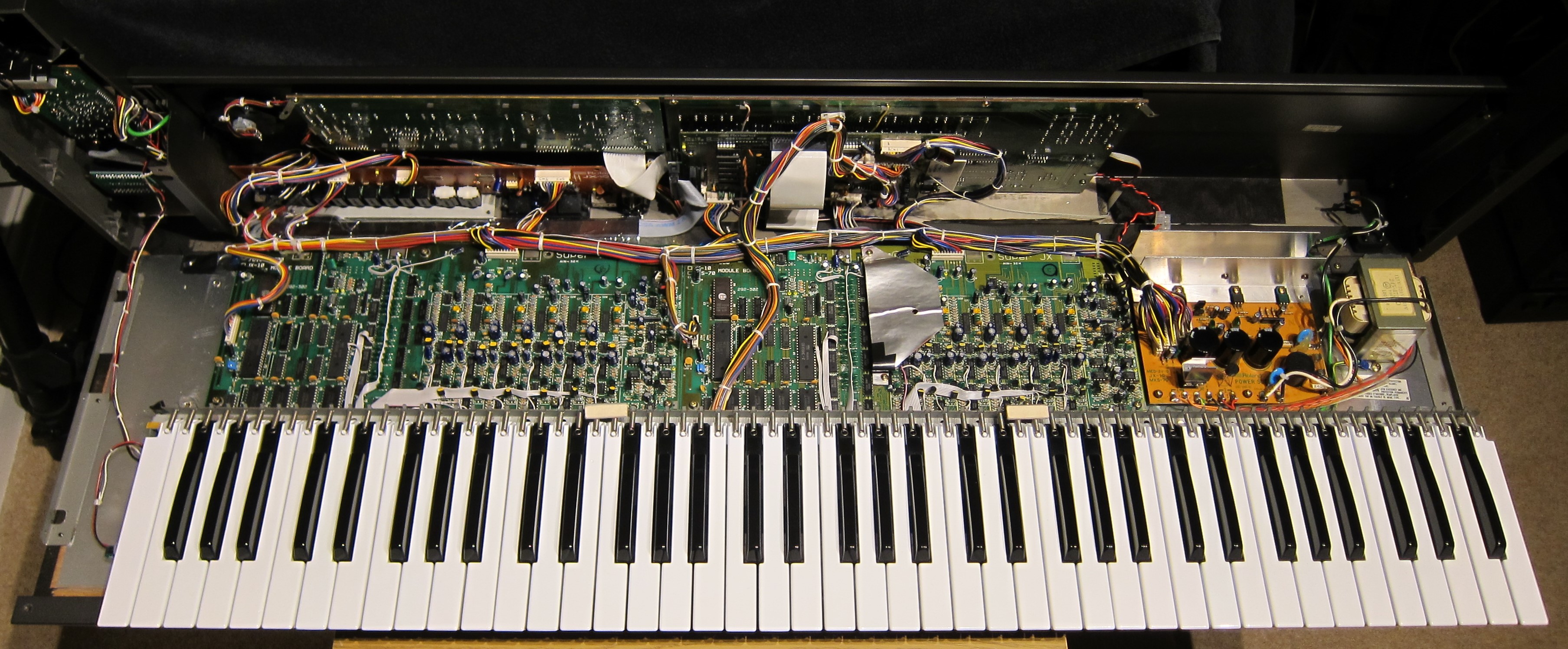
Finally all the contacts are in place so now it is time for refitting the keys.
Keyboard Reassembly
Start with the rightmost key, gradually filling up the keyboard.

Fitting The Springs
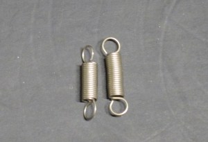
There are two types of springs:
- Short for white keys
- Long for black keys
There is more leverage on the white keys so short springs ensure good tension.
All black keys were done first with long springs. Followed by short springs for white keys.
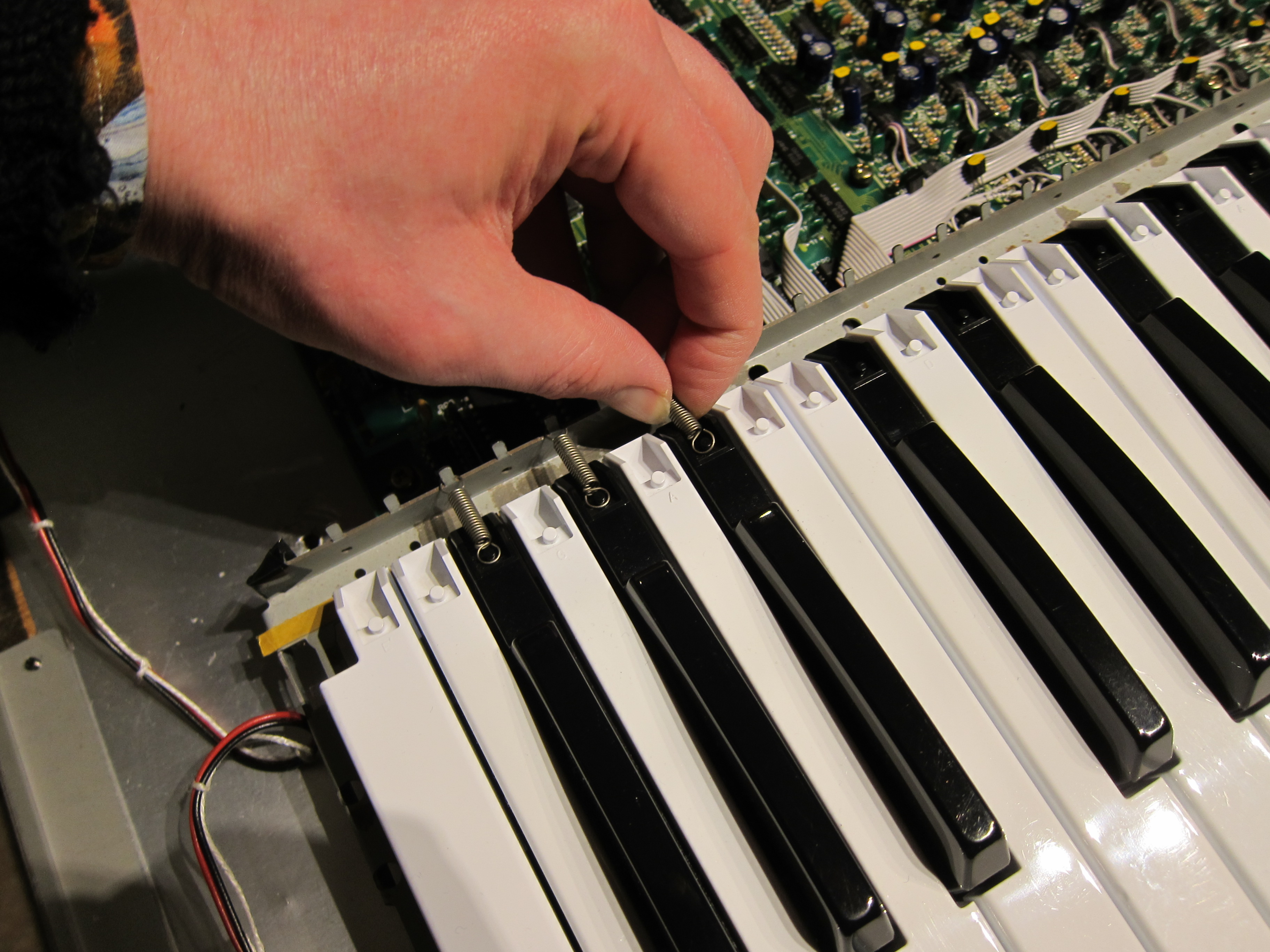
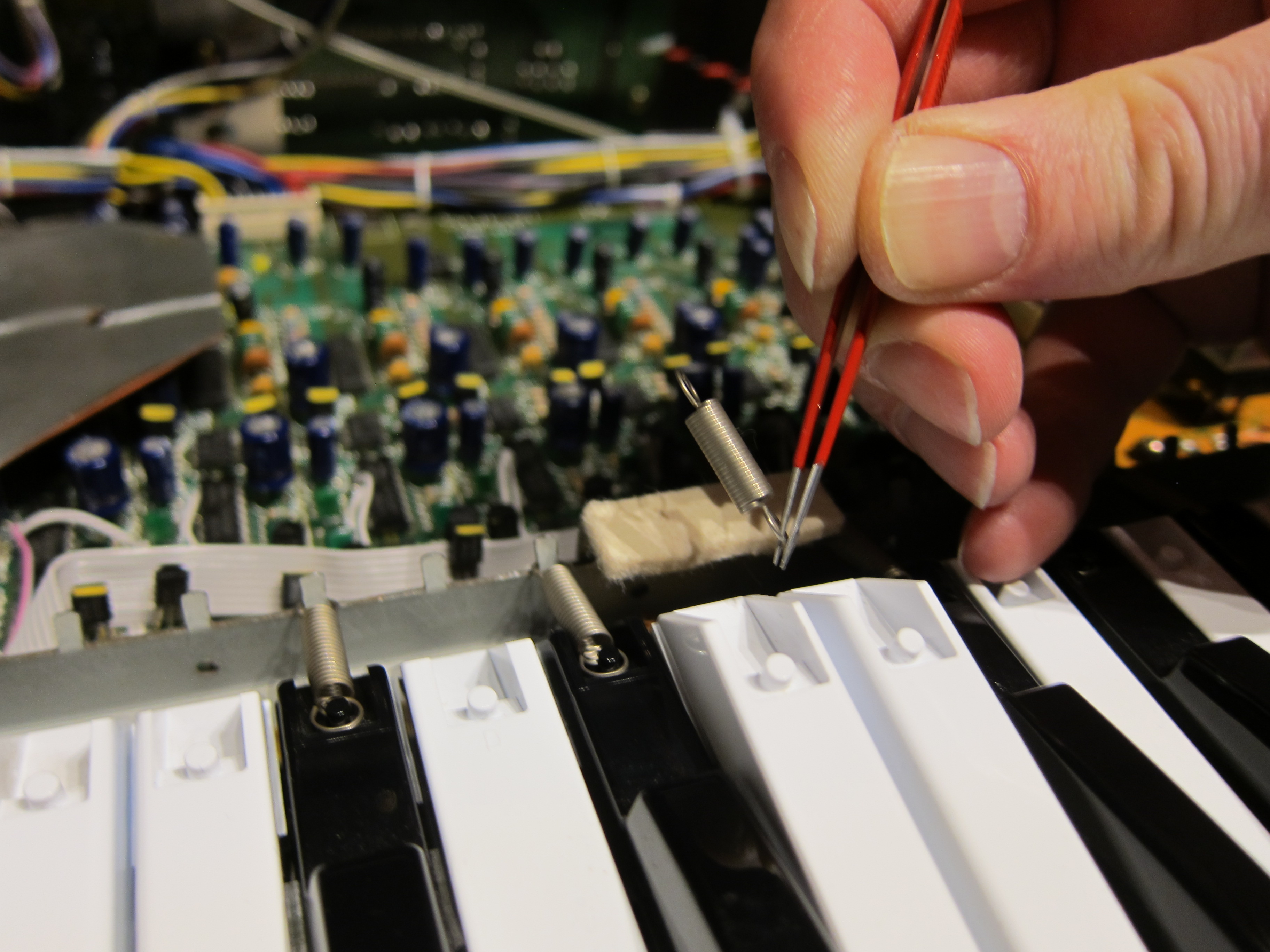
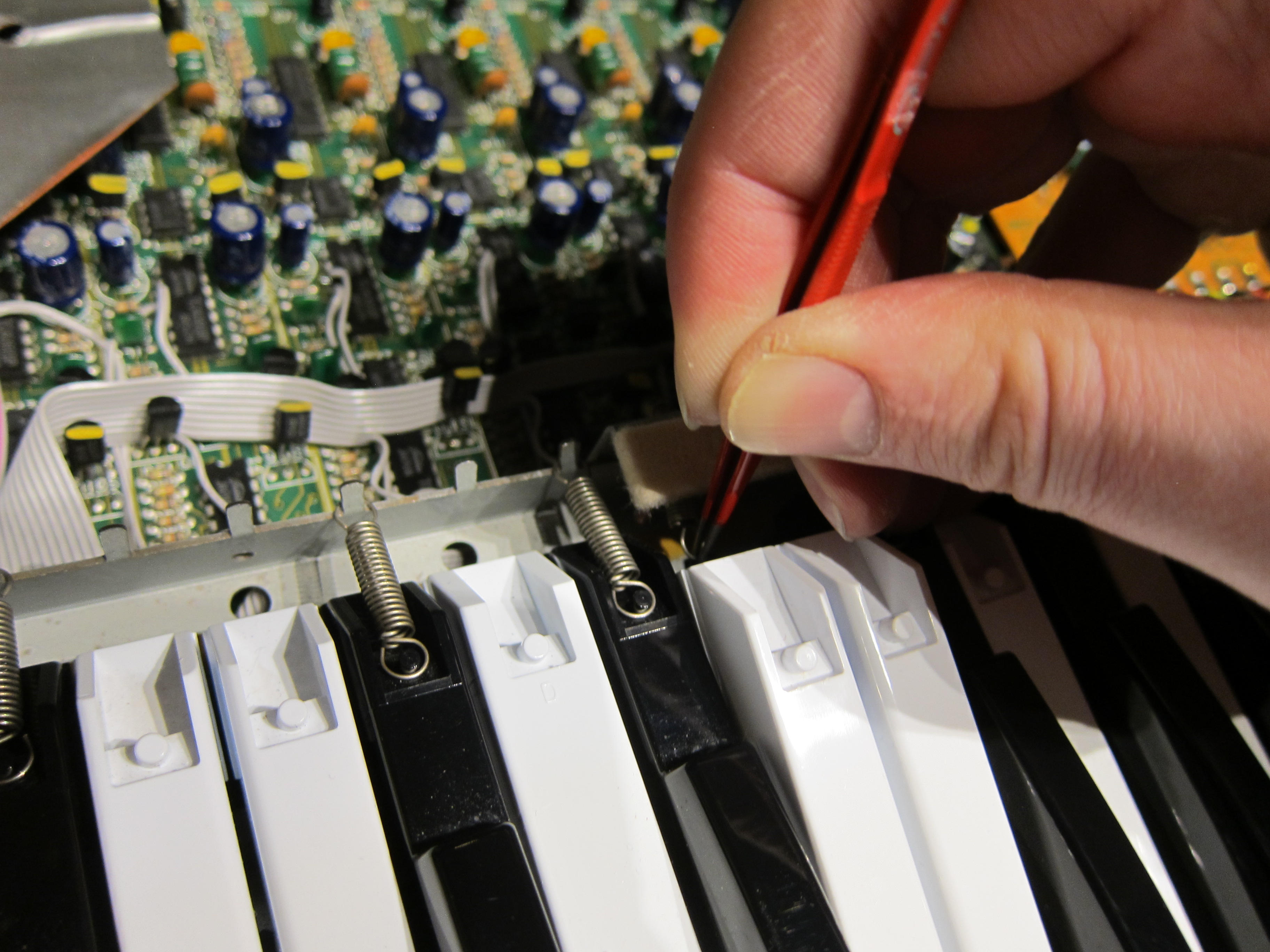
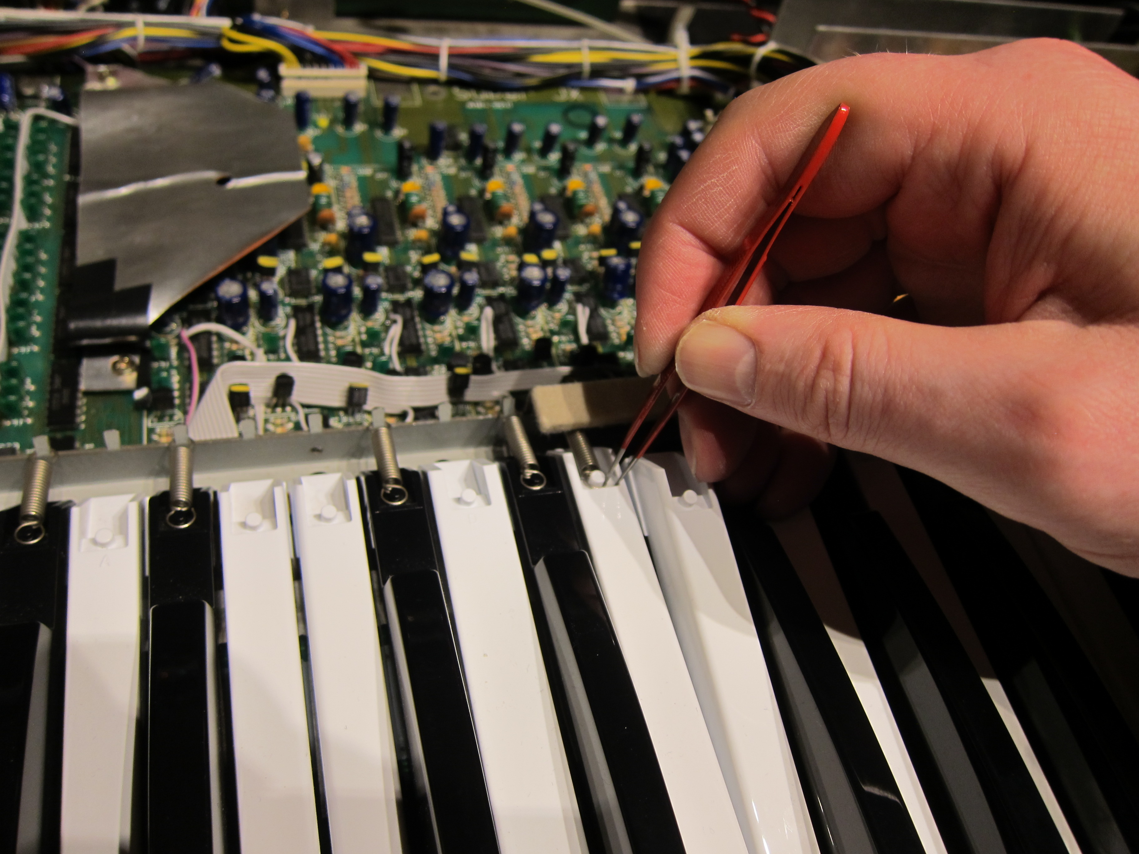
Near the support posts, the springs are attached with tweezers:
- Pull the white key forward
- In the tweezers have the spring up at a sharp angle
- Place the loop on the metal peg
- Push the key down and back
- Pull the spring loop to the key post
- Slide it down the tweezers over the post
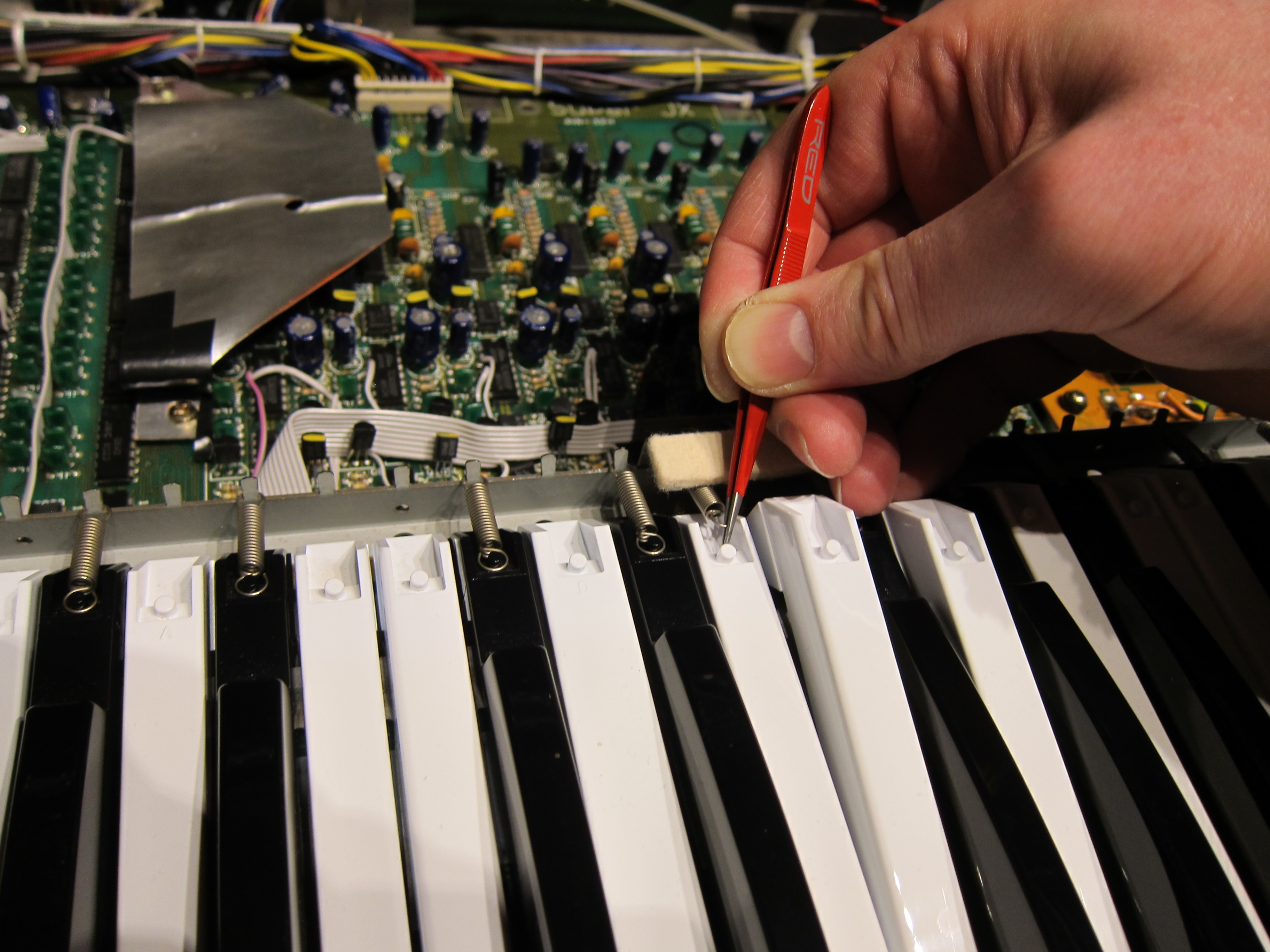
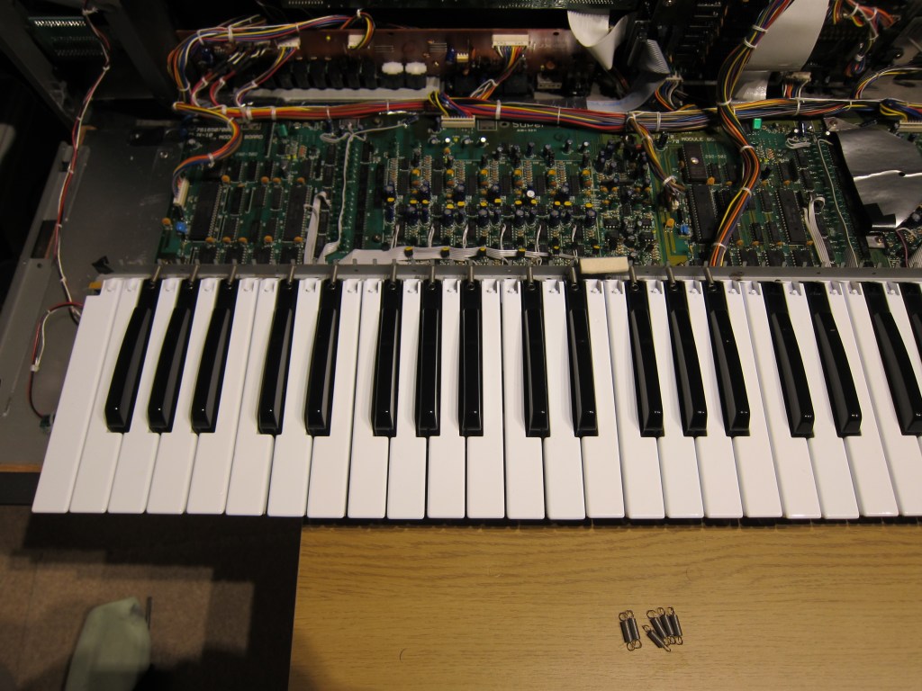
Fit the remaining springs on the white keys.
And that’s it! Test and screw it all back together.
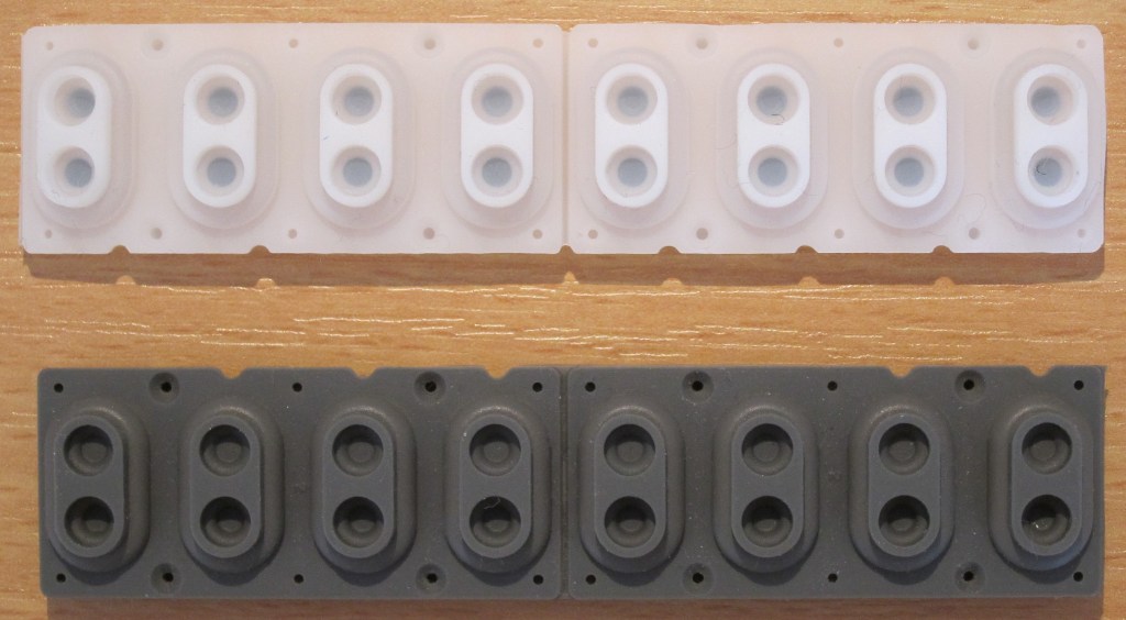
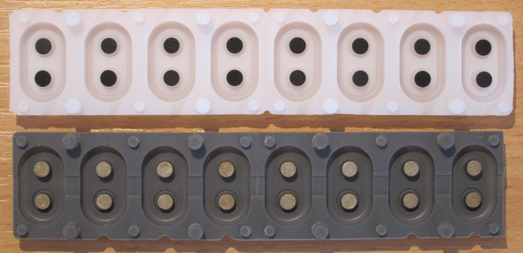
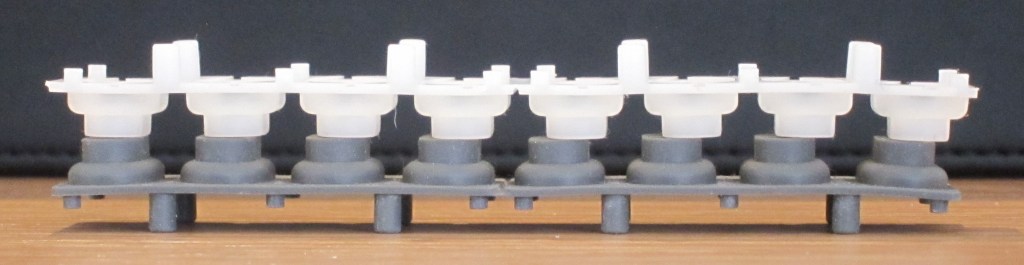
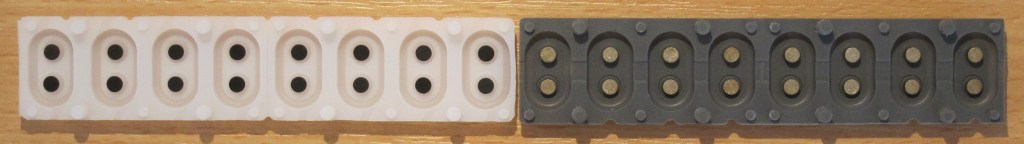
New & Old Comparison
The new contacts are slightly longer but all other dimensions are almost identical.
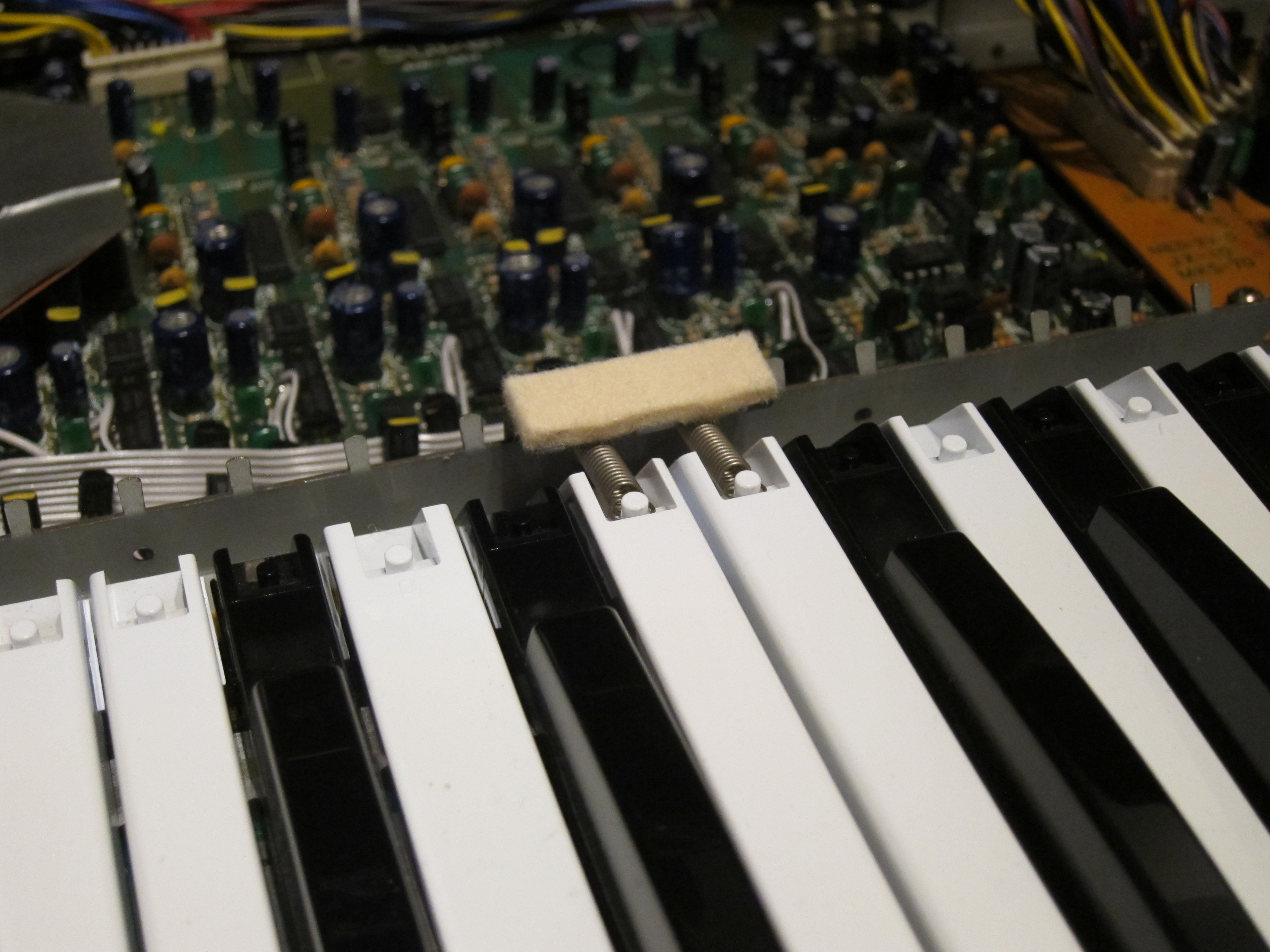
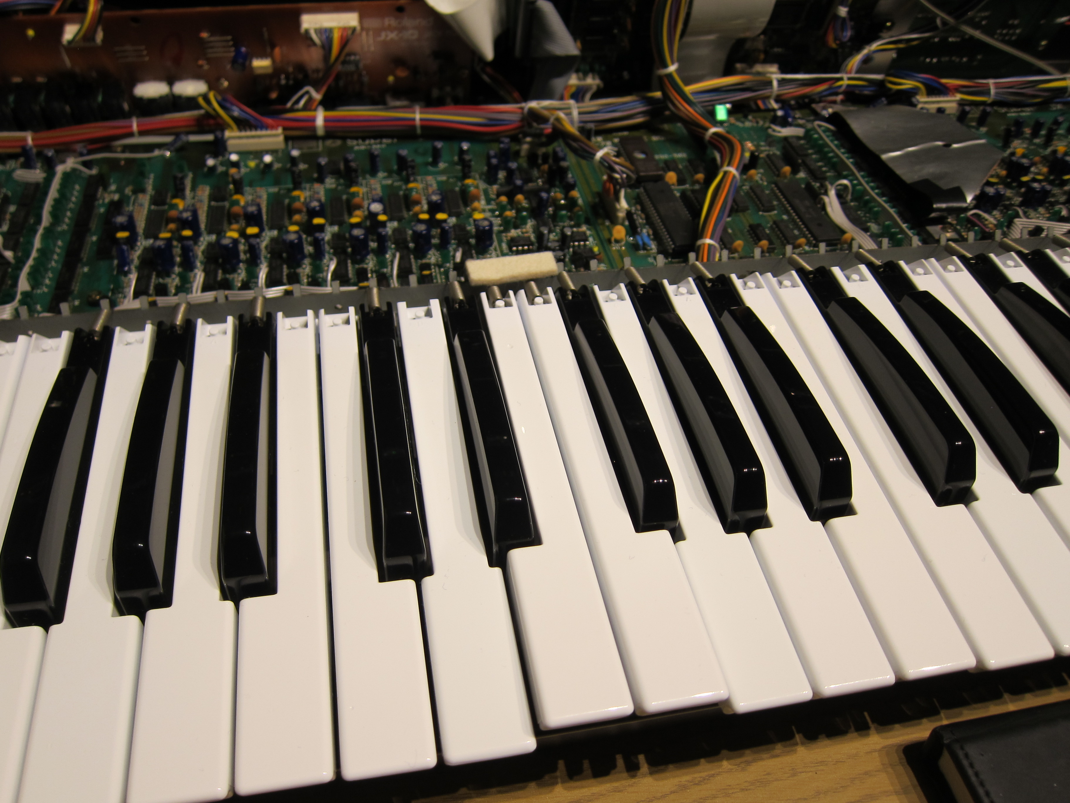
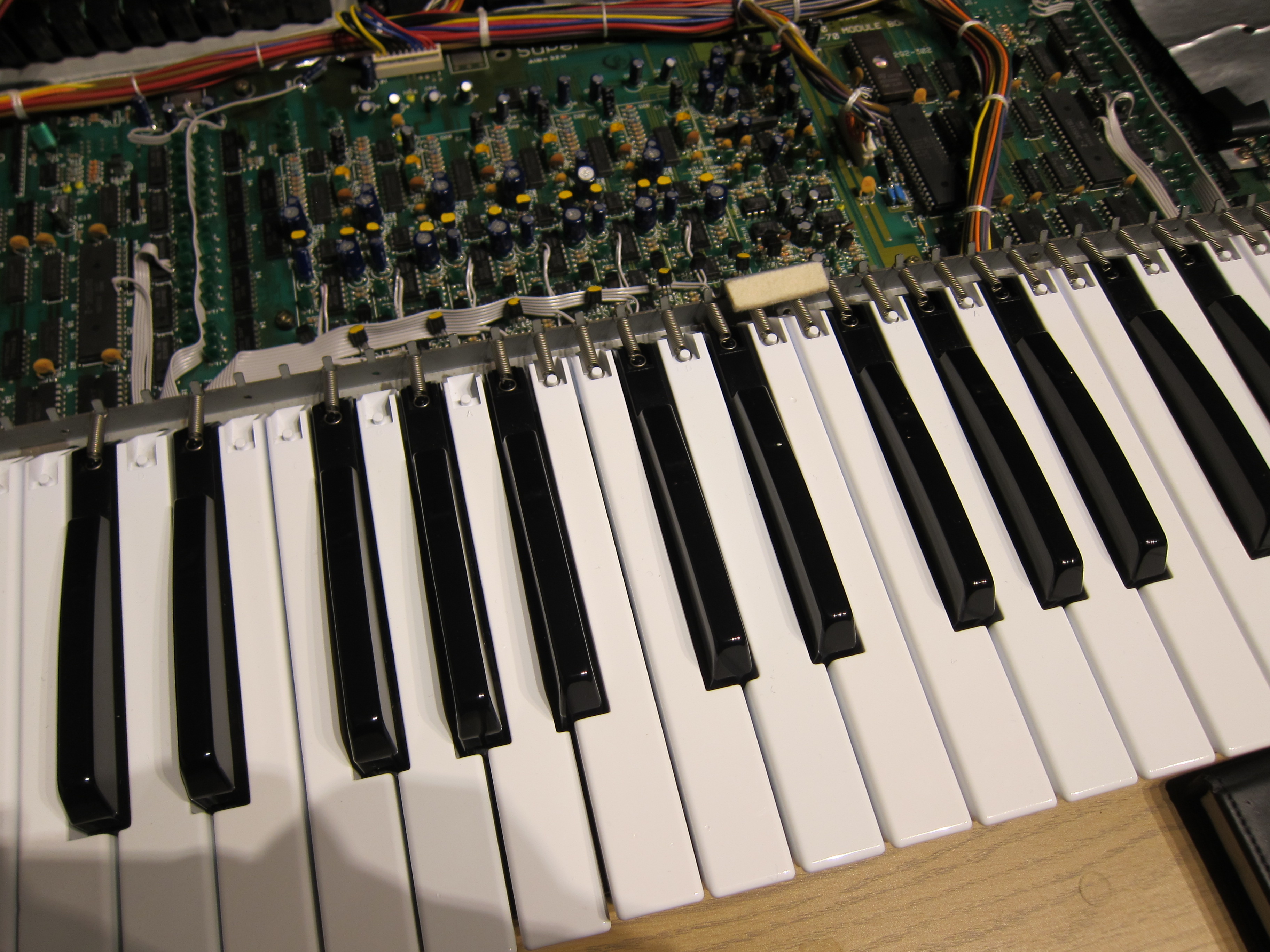
More Pictures
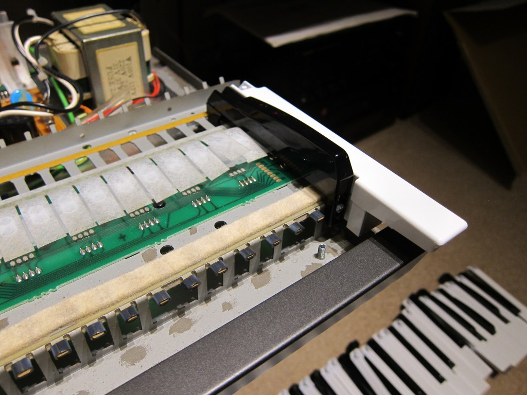
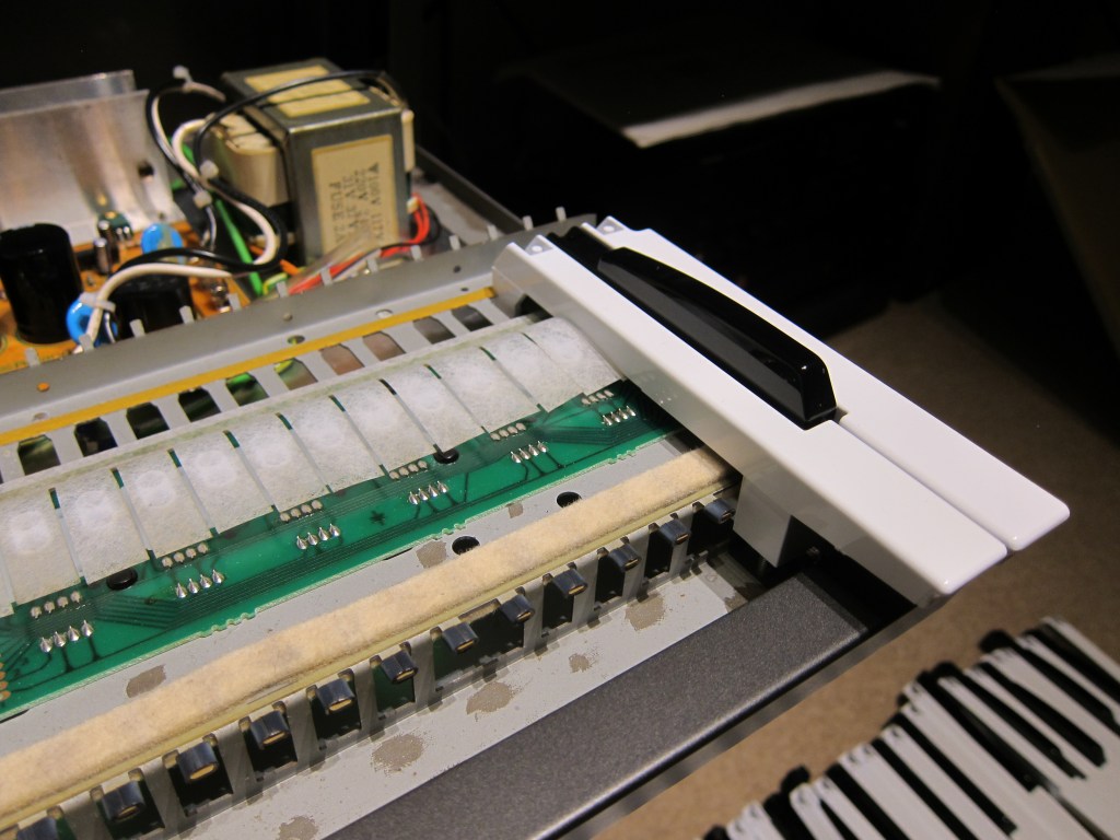
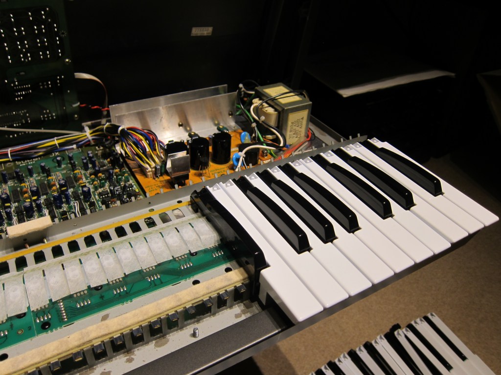
Here are some more pictures showing the initial test with partial disassembly of just one octave.
Copyright © 2017 Super Synth Projects, Guy Wilkinson

You must be logged in to post a comment.