The Analogue PWM enhancement for the Roland Super JX involves adding two daughter cards and wiring to each tone board. This was the first version of the PWM upgrade and is low cost with through hole components. See Digital PWM upgrade guide for the 2021 digital variant that doesn’t have extensive wiring but more de-soldering instead.
Details for the PWM upgrade are here: Vecoven Super JX
Which one you purchase is purely on personal choice.
What Can It Do?
Pads: Check out this demo by Serge Pomorski on SoundCloud: Mother of All Pads
Bass Line: A great use of PWM to make the SuperJX generate sound that it wouldn’t normally be able to do. Oseaan’s Bass Line
Bernd Bruening has developed a set of PWM patches and plays them on YouTube.
How It Works
Special voice board software controls the daughter boards that generates PWM waveforms from sawtooth waves, that are fed back into the tone board to enhance the sound generation capabilities.
In the voice boards, a new high speed 8032 processor derivative is used to execute code up to 3 times faster. Not only can more code be executed but also has an additional benefit for fast and precise envelope generation. The improvement in speed, allows much faster attack envelopes unlike the original Roland design.
There are so many additional options including additional envelopes and LFOs that can be used to manipulate the PWM feature. In experienced hands, the change can be dramatic.
The number of extra parameters are vast, they are described on Fred’s site.
I Got It! Where Do I Start?
To begin the journey, edit a tone and set oscillator type to “PULS”, a PWM value and off you go.
An excellent video showing what to edit to get going yet hear how brutally different the modification can be has been made by Joakim Floke on YouTube.
All of the manuals for the Vecoven upgrades are located on his site in the downloads section, many revolve around the JX 10 but equally applicable to the MKS 70 as only the front panel controls differ.
Installation JX10 & MKS70
A wiring layout guide for both JX10 and MKS70 was prepared to show connections against the cable wire and is here: PWM Wiring IDC Method It is based on the one provided on the Vecoven website.
Check the voltages are in spec on your power supply! See here at bottom of page for how it is done. Sometimes, the PSU IC can have already failed and the instrument still works but will stress devices on the PWM board.
In these pictures you may notice the blue mat and occasional view of a wrist band. This is to keep static electricity under control.

They can be purchased from eBay for very little money. Some electronic parts in the SuperJX are no longer available, taking anti-static precautions reduces the possibility of damage or weakening of old semiconductors.
Mistakes, everyone makes them but check your work carefully. Although it can be boring, the issue with old technology is that parts are hard to find and circuits have little or no protection. For example, connecting to the incorrect power rail or shorting a power rail will cause the power supply to burn out before eventually blowing the fuses in the transformer. The fuses are non replaceable and fitted in the windings, it would be difficult to find a replacement transformer. This is one of the main reasons why a PWM board should not be sticky pad attached underneath a Module Board.
PWM Daughter Board Modification
Modification to the boards can be made that reduces wiring and protects the board from stress in certain failure modes with PSU or memory. It turns out that the TL084 is not necessary and we have proven it is not required. Performance is unaffected apart from maybe a slight improvement in noise figure and reduced power consumption.
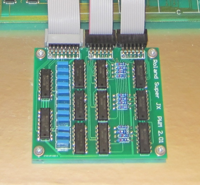
The picture below shows the TL084 replaced with links and resistors changed to 2K ohms. Changing resistors also reduces power consumption without affecting the sound in any way.
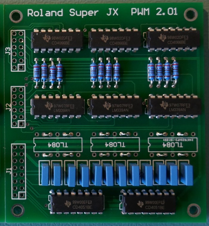
The original design was assuming a slow refresh rate of the PWM value, stored by the blue capacitors in the picture. Fred ended up using a rate of 10ms in final design, so the high input impedance of the comparators is perfectly acceptable.
Module Board CPU Change
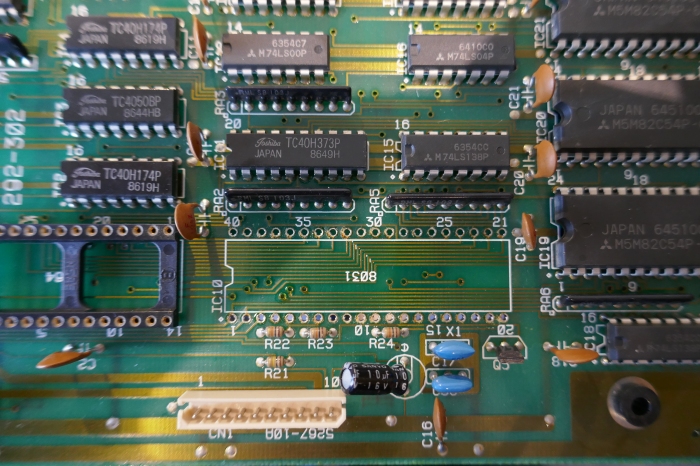
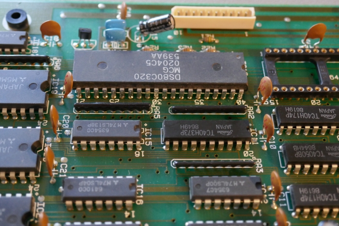
Firstly the tone board micro-controllers are removed and replaced with a Dallas 80C320. Note that turned pin sockets are not provided with the Vecoven kit, if you feel that you may remove the ICs again then it is best to source these.
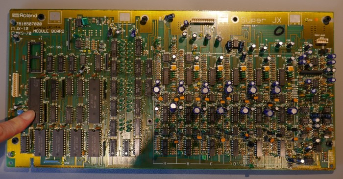
A common problem when removing microcontroller is that through hole plating is damaged and no longer connects top and bottom traces. It can cause very strange behaviour.
Using a Hand Desoldering Pump
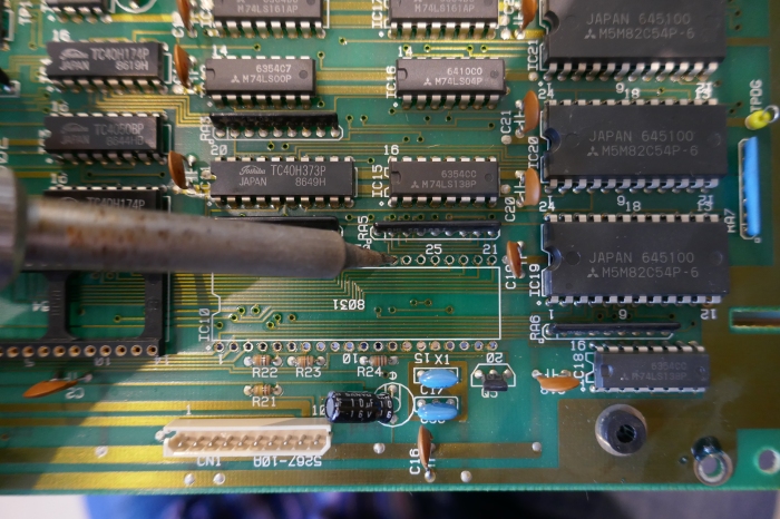
Technique used here is to de-solder all pins with a pump and then cut the pins away from the IC body on the top side of the PCB. The remaining pins usually then just fall out or require a very gentle bit of coaxing with an iron to remove them. You may get lucky and the CPU pops out but don’t force it, otherwise damage to the plated holes can occur. If damage is suspected, ensure that solder reaches both top and bottom side pads of all connections.
Dedicated Electric Pump
It is possible to remove the IC completely undamaged if an electric de-soldering pump is used with careful technique. Ensure that plated through connections are not damaged by careful inspection afterwards.
Crucially, don’t force the chip out, traces of solder can still remain. When pins become a problem, best way is to refill with solder and try again. Also, wiggle the pin to try and crack it away from the edges of the hole, using tweezers on pin underside or a small flat blade screwdriver on top.
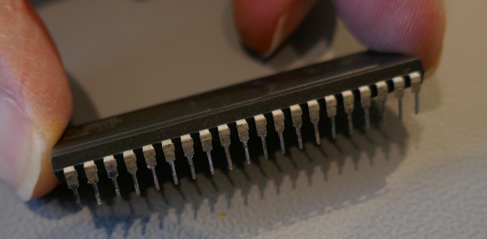
Once the microcontroller has been removed completely, check the pins for any through plating that may have been torn from the PCB. Those pins will need soldering on both sides once new microcontroller is in place.
Tidy up the surplus solder in each hole by melting with a dry iron.
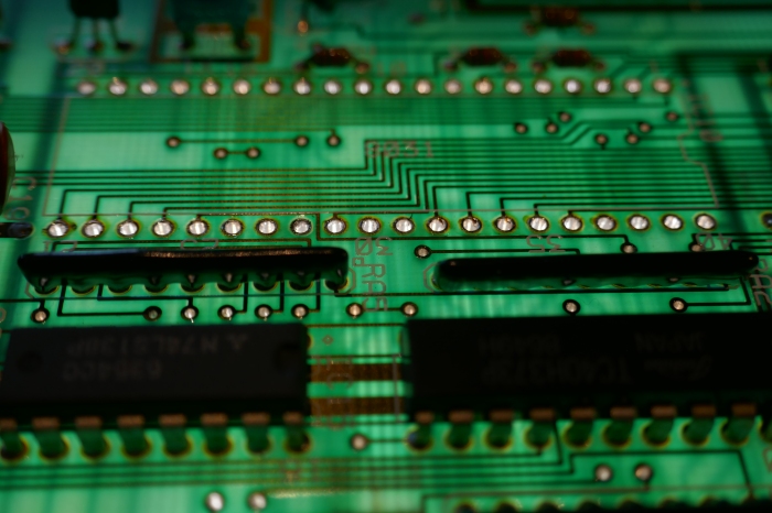
Check the through plating by shining a light through the holes and making sure that they are silvered.
Insert new micro-controller slightly proud so that easy visualisation of solder reaching top side is possible.
Optional Cable Connection
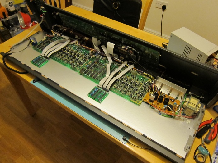
This series of pictures shows how the PWM kit was fitted in a JX10 using IDC cable and right angle pin headers used as connectors. This connector arrangement allows the tone boards to be disconnected if wanted and eases assembly when placing the Tone boards back into position when the keyboard is reinstalled.
Example parts are:
- 4 x 12 Way IDC 2.54mm receptacle: AMP-LATCH 622 series 2-1658527-0, Farnell 3133757, Mouser 571-2-1658527-0
- 2 x 16 Way IDC 2.54mm receptacle: 891 Series 89116-0101, Farnell 2673924, Mouser 517-89116-0101
- 2 x Right angle 72 contact 2.54mm pin header: Harwin M20-9953645, Farnell 1022221, Mouser 855-M20-9953645
- 2m (6ft) of IDC cable grey 28AWG, 1.27mm spacing: 3M 3365-16, Farnell 297318, Mouser 517-3365/16FT
Note that box headers can’t be used due to not enough clearance. Colour coded cable (eg. Amphenol 135-2801-016) can be used but ensure it is compatible with the receptacles.
After making up cable assemblies and cutting headers to size, use a DMM to confirm that there are no short circuits between IDC cable receptacle pins. Use a header inserted in the connector to get a safe connection rather than probe and risk damage.
Solder the headers to the daughter boards.
Note that it is perfectly acceptable just to use normal 24 AWG wire soldered directly to PCB.
JX10 Installation
The MKS70 Installation is different, please scroll further down this page for detailed information.
Daughter boards are screwed in place using self tapping screws and 5mm high 3mm hole nylon spacers. Check positioning to avoid fouling of keyboard struts before screwing in place.
Note that the pictures show the daughter boards too close to the module boards. It makes reassembly very difficult being close.
They are better placed 1 cm further towards the front of the instrument that is away from the module boards.
Note that they are in different positions relative to each tone board, this is because they were placed to avoid cross members in the keyboard metalwork to avoid excessive pressure on the flat cables that join each keyboard PCB.
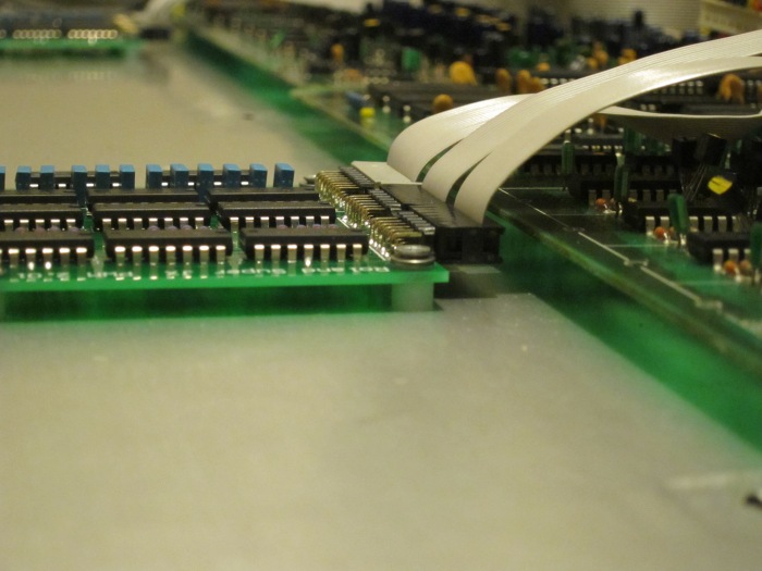
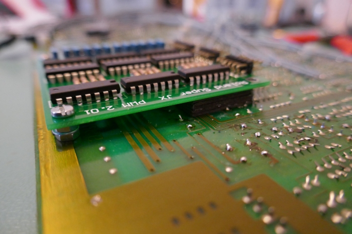
Below is a side view of a daughter board showing the right angle pin headers and the fixing screw that has a nylon washer under a steel washer to provide additional insulation.
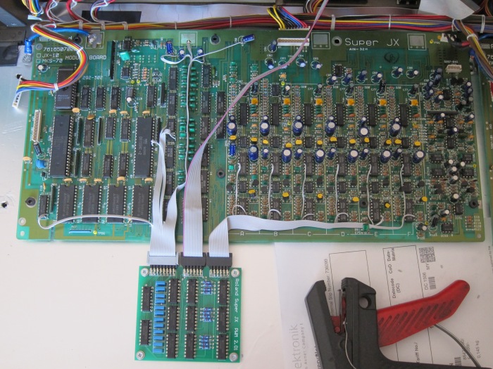
The IDC cables are carefully separated and wired in as per the wiring instructions from the Vecoven Website here: PWM Wiring Manual
If attaching wires directly to component legs, a recommended method is to tin the IC leg followed by wire ends (after stripping) with solder before joining them together with a freshly wet tipped iron. With a little practice this can result in a neat join that is easy to make without having to worry about holding the wire, the solder and the iron all at once!
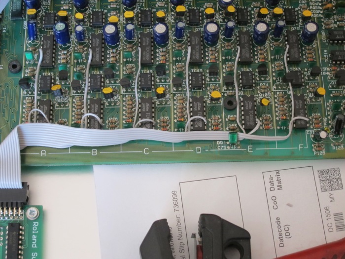

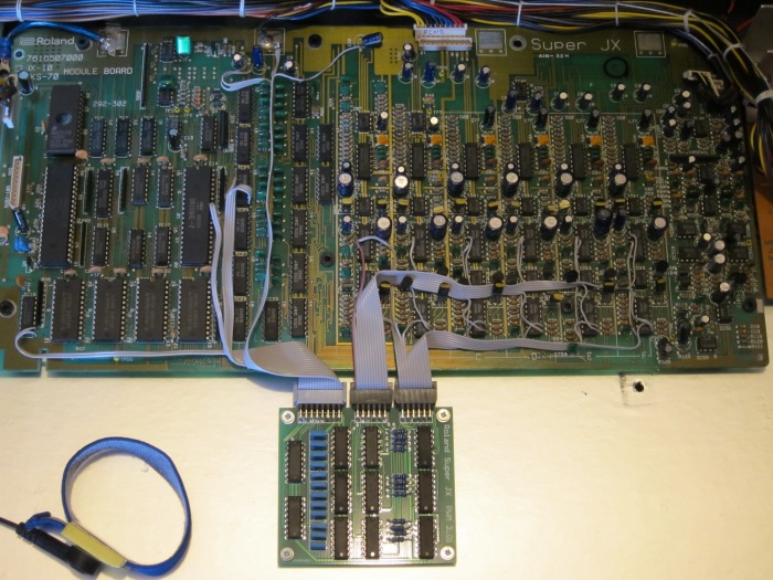
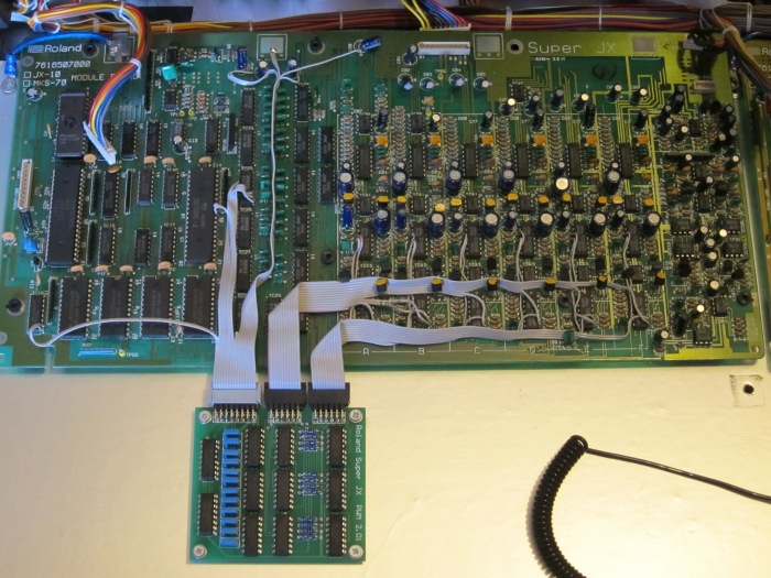
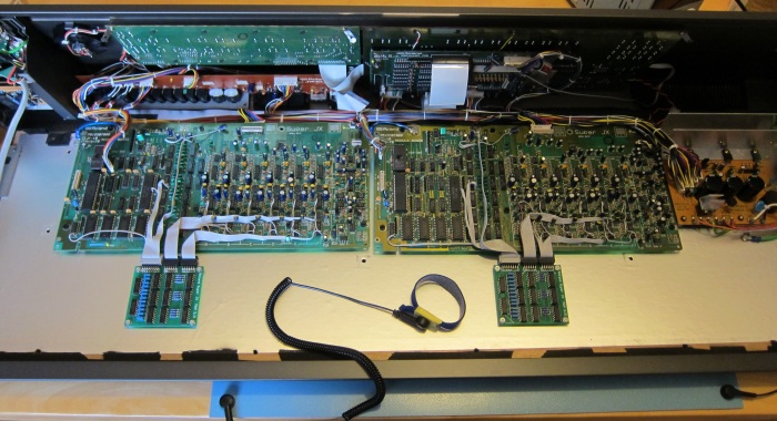
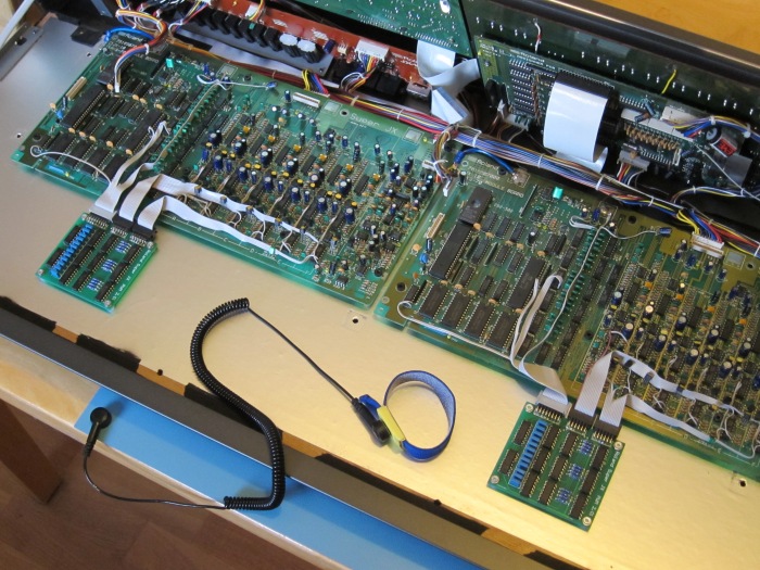
MKS70 Installation
There are many ways to tackle the problem of fitting the PWM mod to the MKS70. This is one of them that achieves the following:
- Shortest possible cable lengths for analogue signals keeping noise as low as possible
- Avoiding positioning the PWM card near the CPU to keep “hiss” low
- Secure the PWM boards to the Module boards for easy maintenance
- Secure method of fixing PWM PCBs to prevent them falling off
- Keep front panel area free for straightforward fitment of display upgrade PCB
- PWM boards are removable for fault finding or returning instrument to stock
The mod is considered easier to do than the one in the JX10.
Re-assembly of the MKS70 can be confusing if you didn’t make a note of where the ROMs and cables go. This guide for the noise reduction mod shows exactly where the ROMs and cables go (see stage 2), otherwise A & B outputs could be interchanged or stereo channels swapped.
Bottom Module Board Wiring
Below, the suggested position of the PWM board for the bottom voice board is ideal. Not only is it positioned directly under the analogue area away from the digital section, two secure fixing points can be easily drilled into the grounding area and the analogue wires are short. there is plenty of space available under the board when installed. The PWM board is mounted slightly “inbound” so that when the instrument is reassembled, it is away from the mains filter.
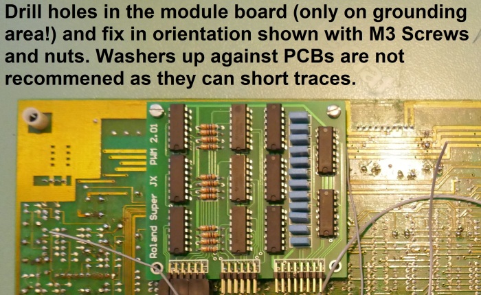
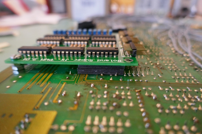
With two fixing points the board is not going to fall off but sticky pads provide additional vibration protection and keep the PCBs apart.
It is a good idea to mark out the underside connections. It is very easy to make a mistake! Unlike picture below, also mark the voice letter too, don’t be like me and do it twice because I wired it in wrong order!
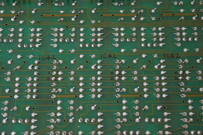
Using the same technique as described for the JX10, wire the IDC cables to the underside pads of the ICs. Tin and trim the wire ends first before attaching to the pad. Trimming is essential because some of the insulation will retreat slightly. It is advisable to renew the solder on the pad in question for a reliable joint.
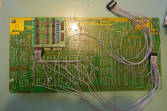
Use off-cuts of wire to hold the loom together neatly, once completed, tie the wires with cotton string/thread. A better alternative is waxed lacing cord like this one here.
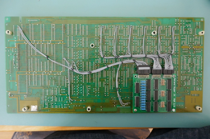
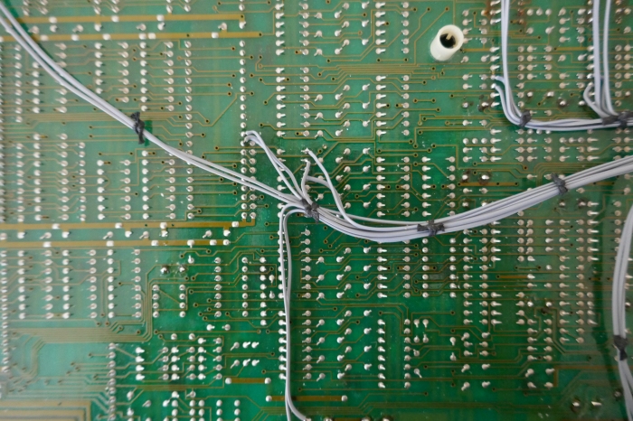
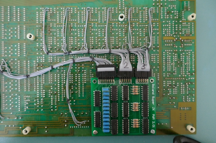
If using the IDC cable/connector method it is necessary to bend some components out of the way to prevent fouling between the two module boards. Carefully and slowly, bend the following components flat in following order: Voice A: Q8 (bend down), C74 (bend down) and C75 (bend up).
Note that this step is NOT necessary if wiring directly to the PWM board without using connectors.
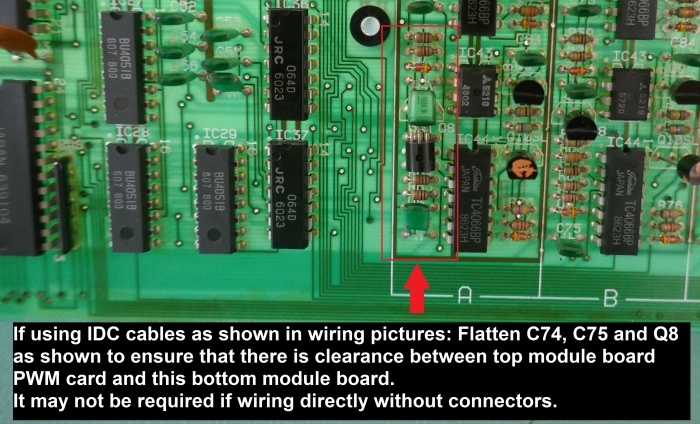
Top Module Board
The PWM board cannot be placed directly under the analogue area like the bottom board because there isn’t enough height available in between the two module boards. It has to be placed partially under the digital area.
The suggested placement below is a good compromise because wire lengths are short and an unused fixing hole normally for the JX10 holds the board firmly in place. Roland left in the original stand off mounts for these holes so one is removed and put in upside down. The upside down standoff is then used with nylon spacers to mount the PWM board along with sticky pads.
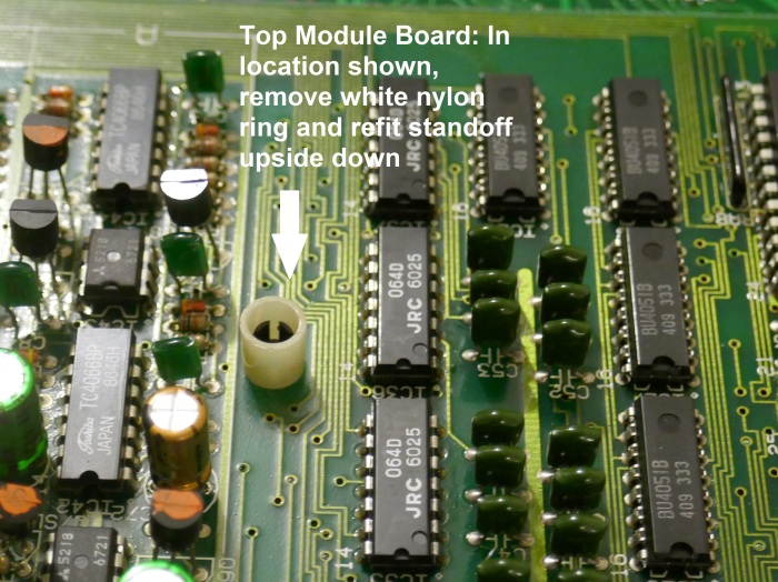
A screw is used to locate the board perfectly in a way that it doesn’t foul any other areas in the case.
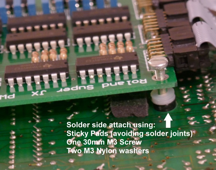
Before doing this it is a good idea to trim all the legs of ICs and components on this daughter card to remove any possibility of short circuits if the nylon washers are thinner than the ones used in the picture.
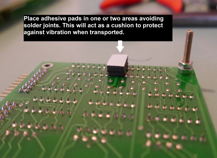
Place a 20mm M3 screw (max 30mm, is shown in picture) in the PWM board and space it off with two nylon washers (ignore the pad in the picture). Use plenty of sticky pads to secure the board in place, however avoid placing pads that on top of solder joints to ensure that the PCB is level. The screw prevents the board from falling off and maintains some pressure on the pads that also provide a cushion effect.
In this example, adhesive pads, Farnell 3382894 were used stacked until correct height was achieved.
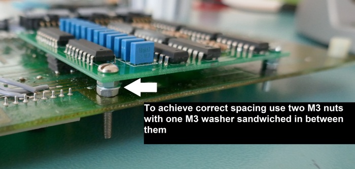
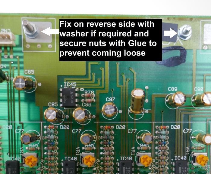
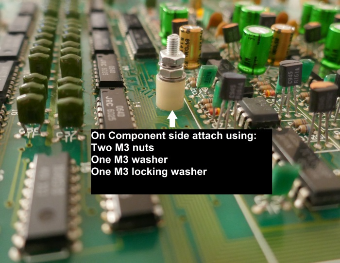
On component side, use an M3 metal washer to press against the nylon standoff. To ensure this is secure, use two nuts and “shakeproof” washer to hold it all in place. A small amount of glue is also advised to hold the top nut in place. If you transport or gig the instrument, anti-vibration measures like this are a good idea.
Wire the connections as per the wiring guide and secure with lacing cord or cotton string.
For this daughter card, do not fit the strain relief to the largest IDC connector as it will foul the transformer when the module board is fitted. It is ok to fit strain reliefs to other connectors if desired.
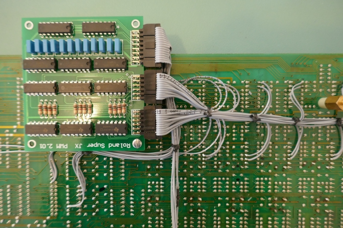
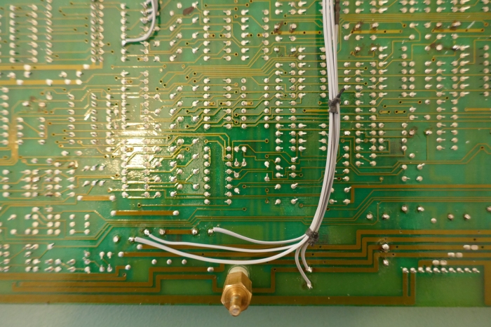
It is a good idea at this point to double check the wiring on both boards using a continuity tester against the guide in the download above. The consequences of an error can be serious and cause damage to the PSU or voice boards.
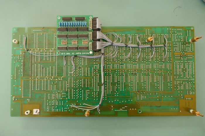
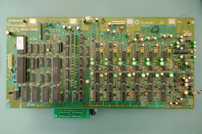
Checking Installation
Place the module boards together with mounting hardware in place. Ensure that components and wires do not foul and that there are no short circuits between the two boards.
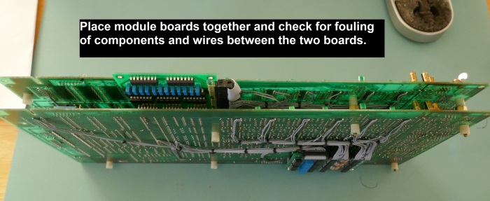
Ensure that the components that have been flattened to make way for the PWM board connector are clear.

Before reconnecting the wires, check that everything goes back together without fouling or shorting.
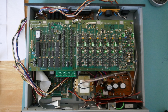
The picture below shows a close up of the resultant position of the PWM PCB on the top module board. The PWM board is away from the CPU and mostly under the analogue demultiplexer. Digital noise coupling should be minimised.
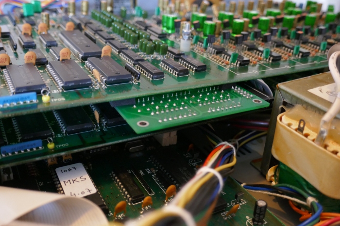
After checking everything is in place, remove the boards and reassemble, not forgetting to fit the new ROM in the assigner.
Copyright © 2020 Super Synth Projects, Guy Wilkinson
You must be logged in to post a comment.