The original display can fail in a few different ways. It is important to remember that the instrument is over 30 years old, there are still many thousands of instruments still in use today and for it to last this long demonstrates Roland’s high quality engineering and manufacturing.
This information is intended for interest only but could be used to work out a fix for a faulty display.
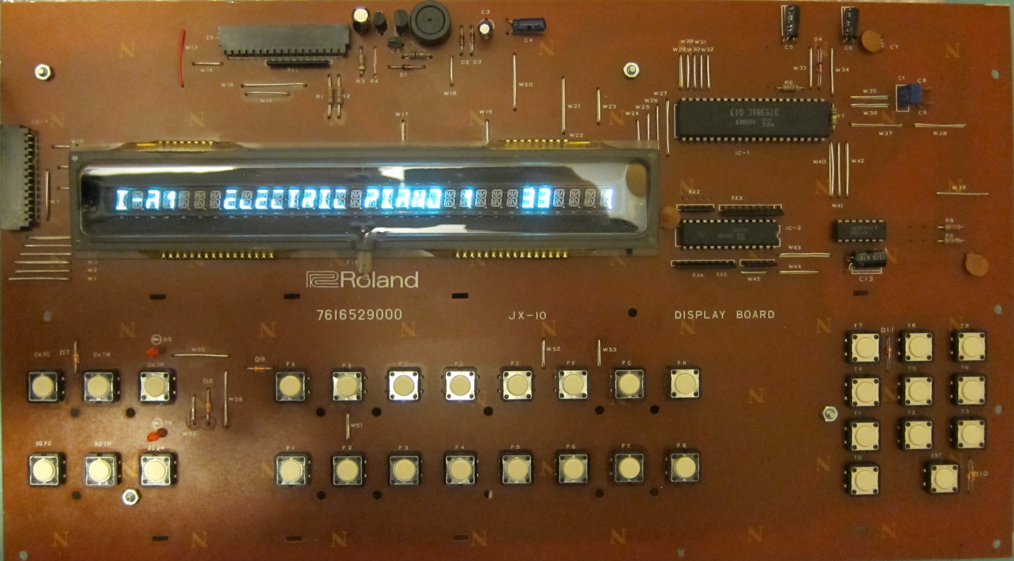
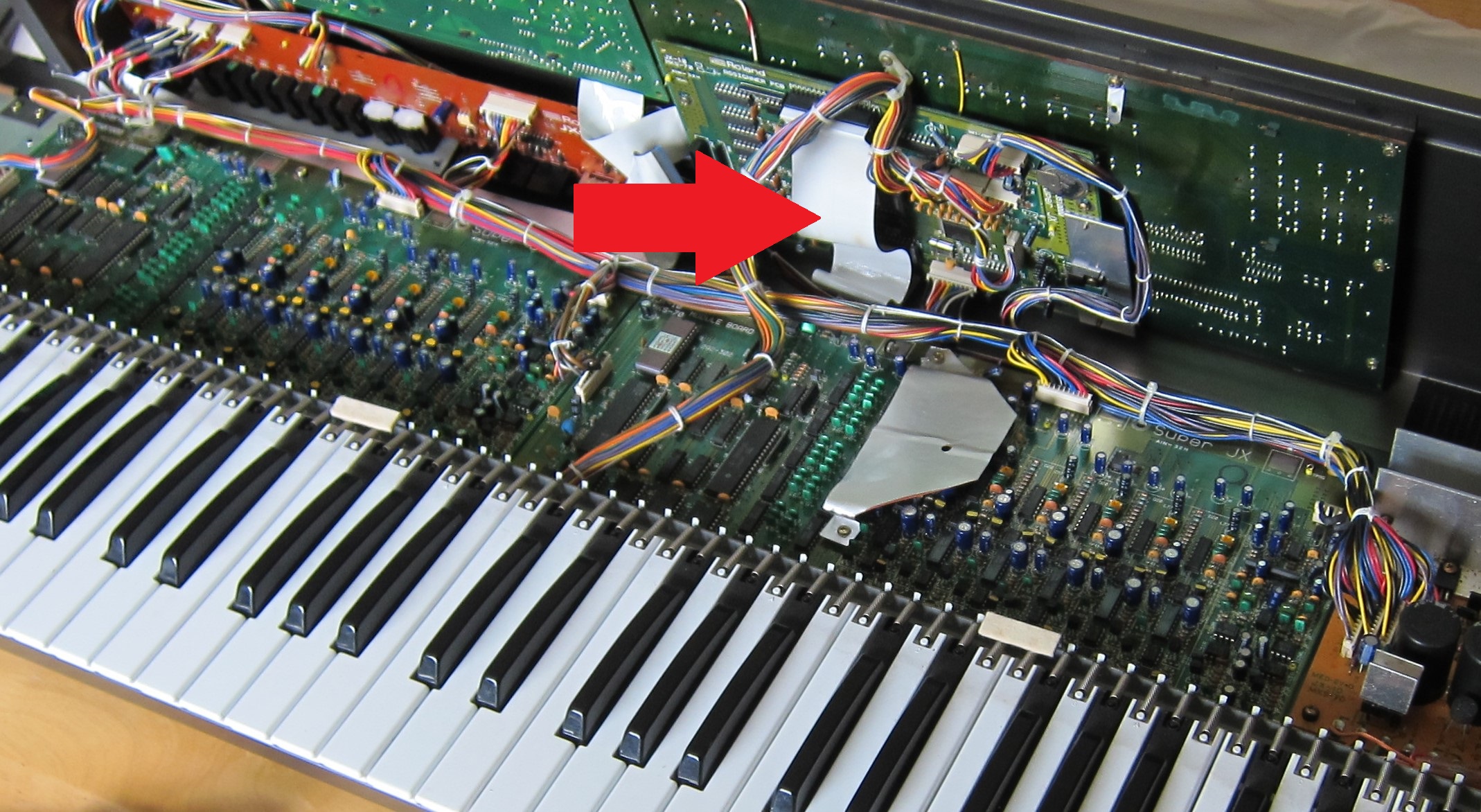
The pictures below are from a Roland JX10 display board that had two faults: Wire link corrosion causing dry joints and VFD bond out connection failure on two segments, of which one segment was temperature dependent.

FIP Transformer
The most common failure mode where the transformer corrodes internally and breaks down. A replacement is available on eBay and is also known as “FIP Coil”..
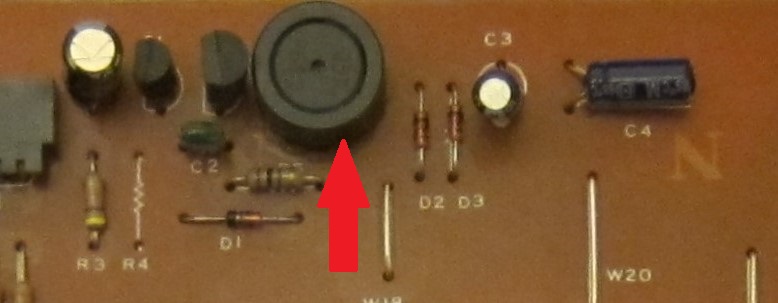
Issue: All segments lit at high brightness. Display not lit at all.
Fix: Replace transformer.
VFD Heater Filament
VFD heater filaments have a continuous use design life of 20 years. If the instrument has been on for most of its life then they can burn out or become weak and break due to shocks when the instrument has been transported. They work just like filaments in light bulbs except that they do not run at such a high temperature. This type of VFD is no longer available and so either replace the display or use an old one from a donor instrument. Note that the MKS-70 and JX-10 use different display types and they are therefore not interchangeable.
Issue: Display not lit at all. Display partially lit due to one filament working.
Fix: Replace VFD from donor instrument or buy new display retrofit shown on this site.
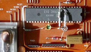
Dry Solder Joints (JX10)
The JX-10 Display Board is a single sided PCB with many jumper links and is vulnerable to dry joints. When fixing dry joints, it is important to remove the old solder then remake the joint rather than just reheat (“reflow”). This is because the oxidised metal on the surfaces will move into the joint and make it weak. On some boards, corrosion of the wire link has been seen that makes the joint not only “dry” but is almost impossible to renew solder without abrasive cleaner. Links carrying the power rails seem to be particularly susceptible. In the picture, the 7 – 10V unregulated supply has been affected and the link has already been replaced with red wire. MKS-70 is least affected by this issue because it has a double side fibreglass PTH PCB.
Issue: Display not lit. Missing segments or digits (less likely).
Fix: Remove and replace solder. Replace wire links that are corroded or difficult to solder.
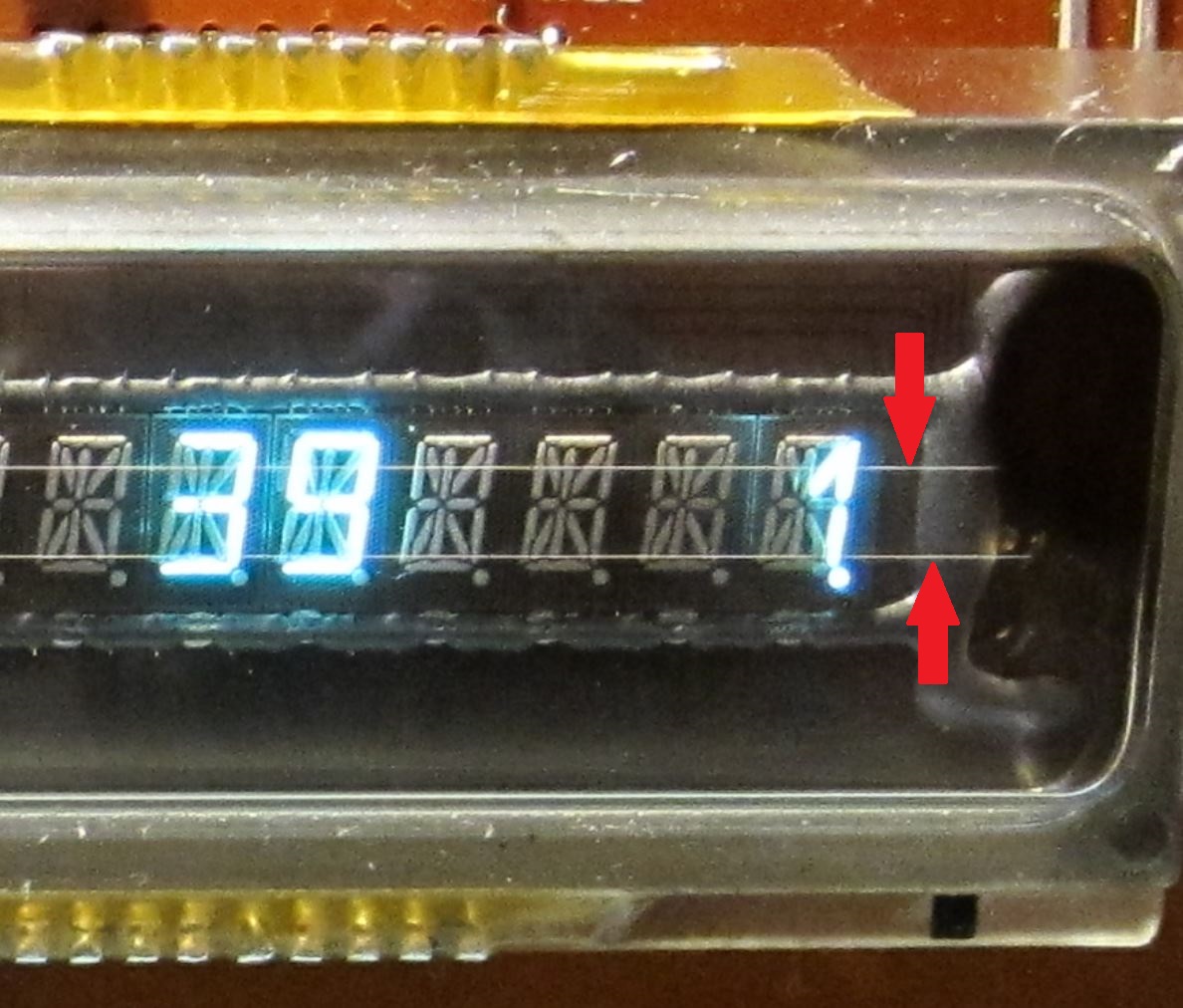
VFD Bond Out Connection Failure
The Vacuum Fluorescent Display has bond out terminals that press onto the traces on the glass substrate. These are protected from effects of humidity by a layer of epoxy. In some displays the epoxy may be overly thin and allow corrosion to occur, or over time, mechanical stress from natural temperature variation can make the interface electrically weak and eventually fail. In one case this was proven by applying freezer spray on the contacts and observing missing segments reappearing. Using freezer spray would probably accelerate the process of degradation or make the epoxy brittle and is not recommended.
Issue: Missing segments or digits.
Fix: Replace display. Alternatively, if feeling brave, maybe remove epoxy and apply conductive paint to the broken connection (not tried yet!).
Micro-controller & Latch IC Output Failure
Sometimes the output drivers in IC1 or IC2 that drive segments and digits can fail open circuit or high resistance. Likely cause is IC bond wire failure or a short circuit fault damaging the output.
Issue: Display lit but segments or digits missing.
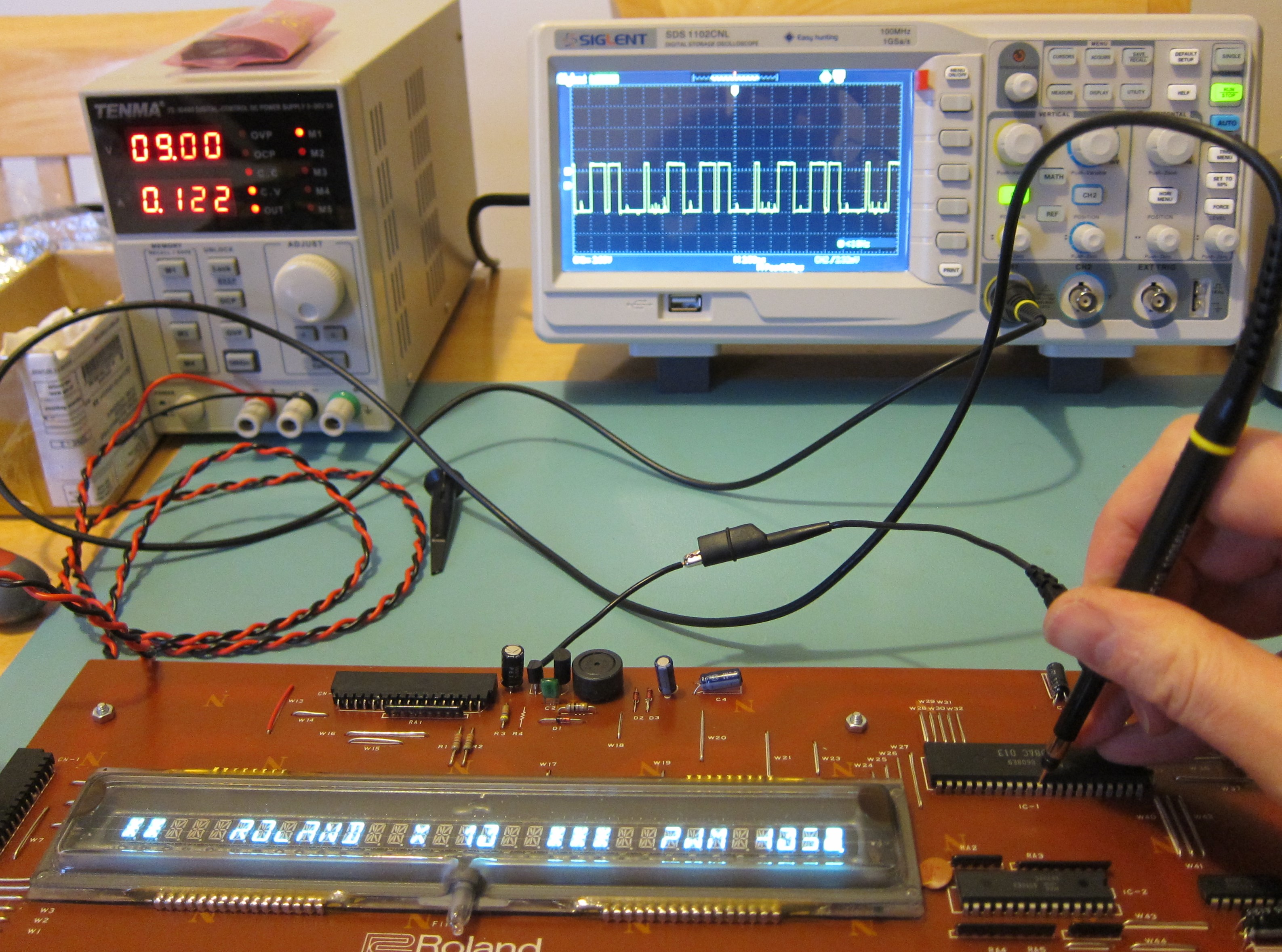
Fix: Replace IC from donor instrument. Replace entire display with retrofit. Or if the output is just failing on lack of drive capability, you could be clever and design a booster circuit like in the example picture below!
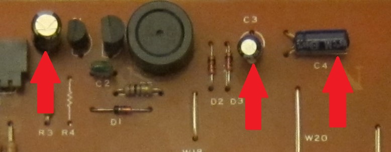
Capacitors
The electrolytic capacitors used in the circuit around the FIP transformer can dry out. If replacing them, ensure that same or higher voltage rating is used.
Issue: Dim or non-working display.
Fix: Replace capacitors
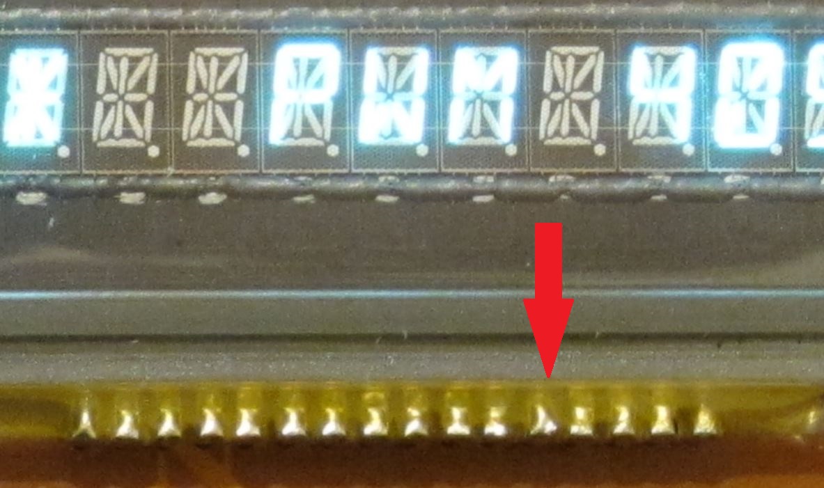
Flat cable
The flat cable between the display board and assigner can be damaged easily. The connector “fingers” can lift up and touch neighbouring wires when re-inserted into connectors. If removing, ensure that the contact fingers don’t lift up and move when inserting back into connector. It is the least likely failure mode because only 4 connections affect the display: ground, power, data and clock.
Issue: Display not lit.
Fix: Replace flat cable, it’s possible to buy replacements intended for printers, they are weaker and cannot cope with tight folds but can work ok. Alternatively, use IDC cable solution for a robust method.
Copyright © 2017 Super Synth Projects, Guy Wilkinson

You must be logged in to post a comment.