Having picked up a broken Yamaha EMP700 effects processor for £35 with display and audio faults, after a clean up, display capacitor replacement, dry joints around jack sockets and a new battery, I now have a pretty decent unit that can be used in line with an analogue synthesizer in my “DAW free” set up. Here I document a quick set of pictures showing the steps taken and using ceramic capacitors instead of electrolytic for a much more elegant and longer lasting fix.

The EMP 700 doesn’t sound as good as a modern Lexicon or plug in, but does add a digital character of it’s own that partners very well with old analogue synths. Interestingly, excellent at making haunting sound effects and filling out pads in such a way that they can sound rather mysterious. In summary, I love it!
For it’s time, the EMP700 was a pretty decent effects processor and apart from the display capacitor choice, the design is extremely well engineered and all other capacitors, usually Nichicon, are high quality and tested out still perfect after 30 years.
A Yamaha EMP700 service manual can be found here.
Popping The Hood
Remove all screws on top lid and marvel at the quality layout and engineering.

Removing Display Board
After removing 2 screws tucked in on the inside of the base slide off the the display panel, remove the rivets and untwist the metal spike.
When untwisting the metal spike, take a great deal of care not to damage the PCB traces whilst doing so, repair will be extremely difficult if these are scratched.

Rivets holding the display board are easy to remove, just lift off the head and the whole thing pops out.

The display is attached by a couple of edge connectors to the main board. Take care not to pull on the display end as stress across the board can damage the contacts to the LCD. just pull on the right hand side of the PCB whilst giving it a wiggle. It is quite tricky to get off.

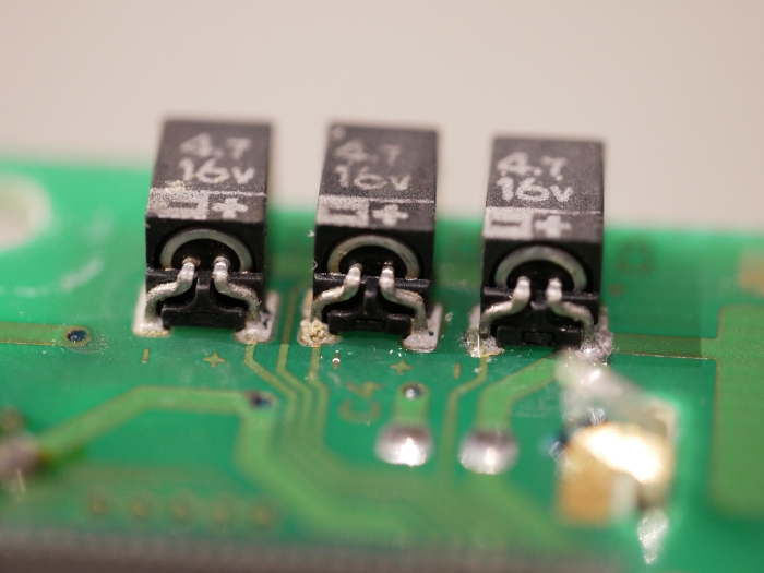
One the PCB is off turn over and you can identify the 3 electrolytic capacitors used for generating the LCD driving voltages in the charge pump circuit.

Electrolytic Capacitors

Close examination will show that the capacitors have leaked.

Capacitor Removal
They are a little tricky to remove without damaging the pads and traces, the best way is to wet the soldering iron tip with lead solder and lift off one pin at a time. Remove the solder and clean up the pads. Cleaning was a little challenging as the electrolyte had cause a little bit of corrosion. IPA, flux and re-tinning then some braid to flatten, prepared the pads well.

Replacement Capacitors
Modern ceramic MLCC 4.7uF 16V 1206 capacitors were used for the fix. They fit between the pads on the display board beautifully and will outlive the instrument. Some fixes on the web and YouTube show capacitors with long leads, but the risk of short circuit to power rail trace and lifting the pads is high because solder resist doesn’t insulate reliably at any voltage, being only a few microns thick.

Fit Capacitors
The new capacitors are soldered into place and are perfect for the job and cost very little money.


Testing The Display
Plugging in the display board and testing revealed a now working display but time is taking it’s toll as can be expected. The board was removed again and the clips on the rear of the display were tightened up to improve the compression force on the LCD zebra strip connectors. After a couple of weeks, the display came back completely.

Audio Issue
When Jack plugs were inserted, the audio was either low gain or intermittent, so the main board was removed for inspection.

The solder joints around the jack sockets had fractured, solder was removed and replaced with new.

Battery Replacement
It was cheaper to obtain a holder and super long life Renata button cell than replace with original type. The chosen cell has been proven to last 30 years in Roland instruments, despite manufacturer claim of 10 years. We chose the CR2450N because it is likely that it will outlive myself. The holder was a little larger and required a small mod to the board to accommodate. Some clear silicone sealant was used to further secure it.
When undertaking a battery change, there is no point in losing the settings, simply add another battery in circuit via a resistor (470R to 10K) to the input of the diode. The one in the picture is stored in a bag to prevent short circuits and is simply an old battery from a JX10.
Copyright © 2021 Super Synth Projects, Guy Wilkinson


You must be logged in to post a comment.