The fabulous Korg M1 was made in huge quantities to a price, it is a heavily value engineered product yet no corners were cut that affected reliability. The display however is relatively poor quality and is very much of it’s time when all character LCDs were like this.
This article shows how the Korg M1 LCD is replaced with one using an OLED module that has been specially made for the JX10/MKS70 and JX8P display retrofit projects.

For the best possible visual experience, fitting involves using a tool to trim the display mounting pillars that are molded into the plastic front panel. A ready made and fully tested assembly is available that transposes all the connections from the OLED to the new mounting arrangement.
All of this work was trialed on three Korg M1 instruments owned by, Jonathan Williams. Jonathan has refurbished the instruments and did all the hard work upgrading the displays too.
Availability
It is not known how other OLED display modules perform on the Korg M1, we are happy to supply display modules if users have the confidence to fit them. We do try to make the process as painless as possible, see our Availability page for supply of parts or a fully built and tested assembly used in this guide.
Disassembly
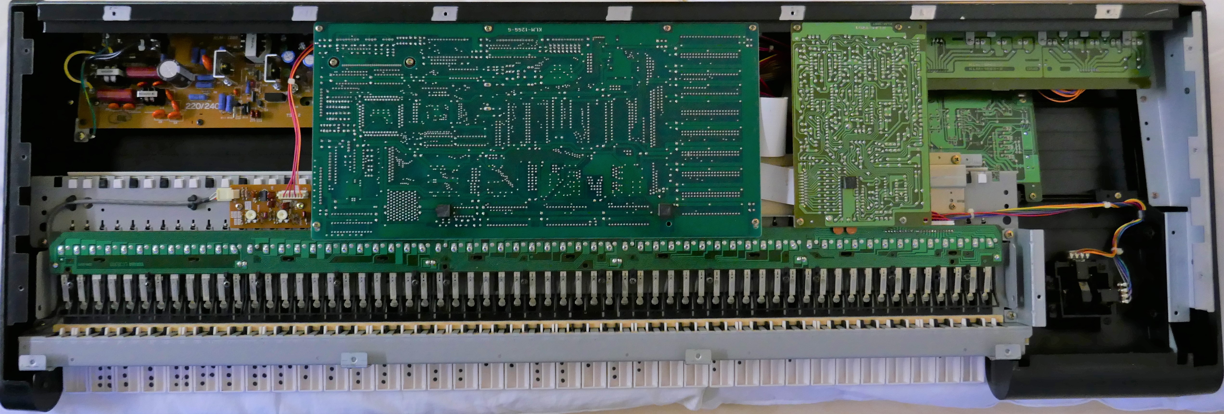
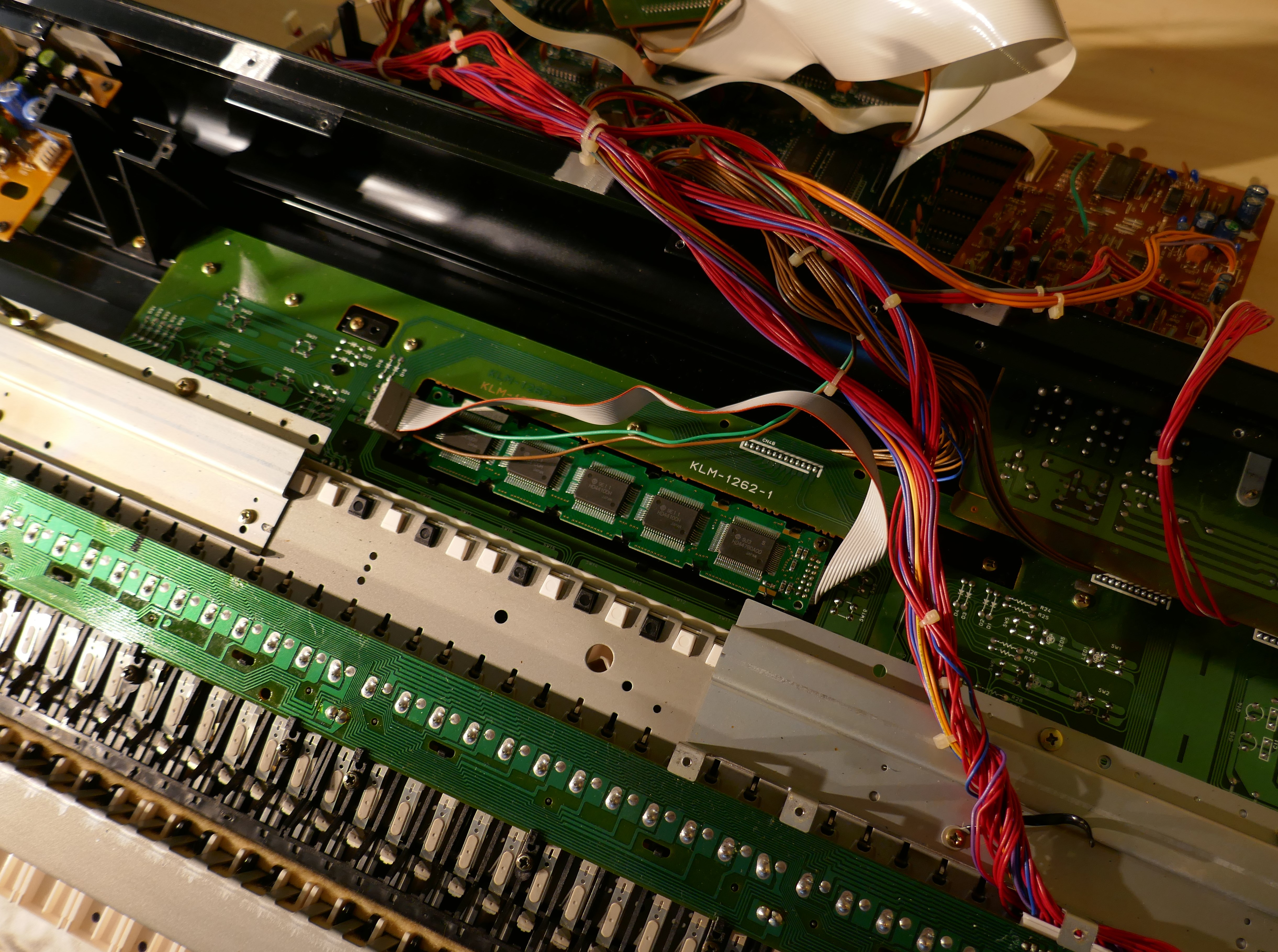
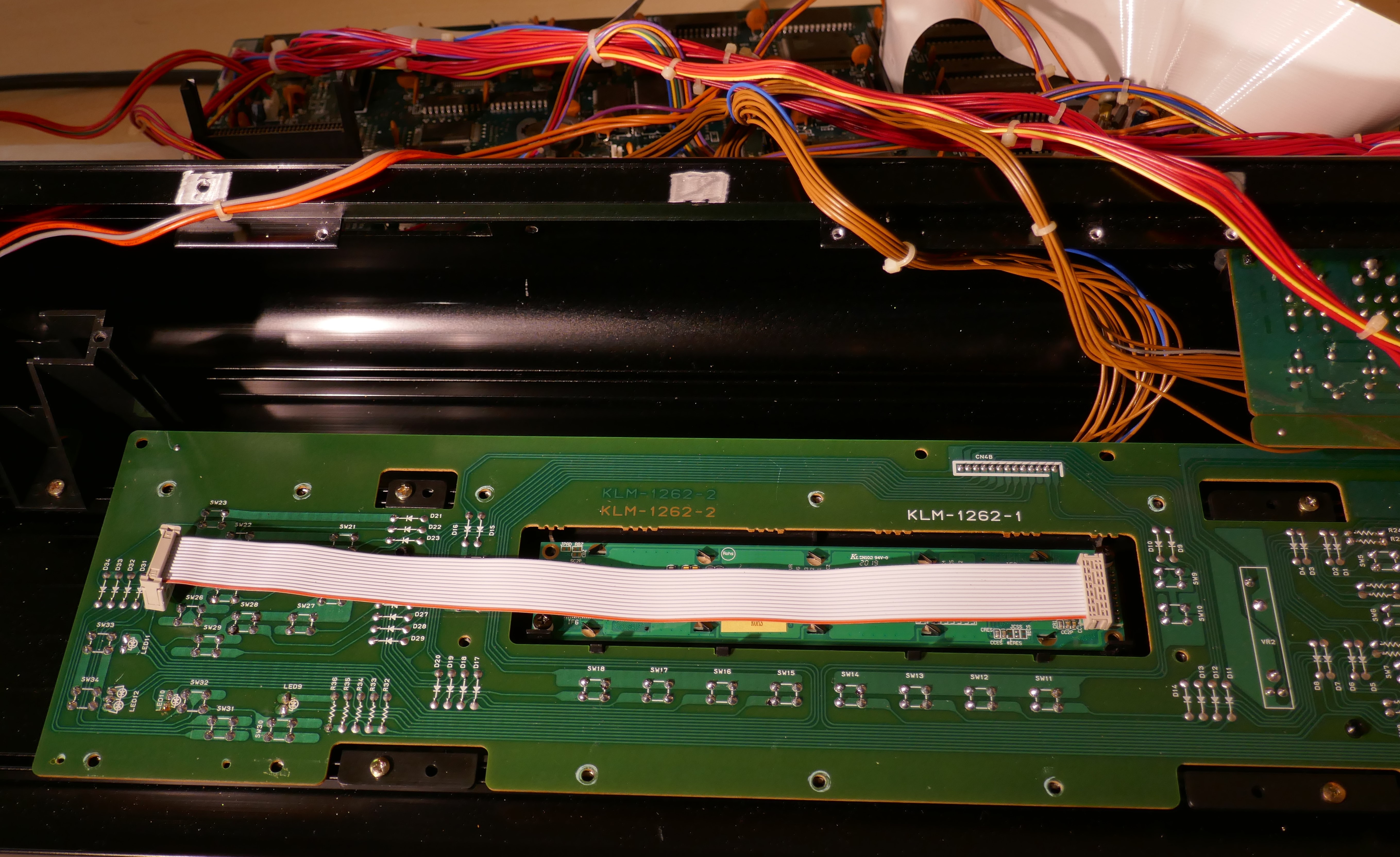
The instrument is disassembled from the rear just like most synthesizers of this era. During installation, the synth was rested upside down on two pillows to protect from damage. Picture below shows what is seen once screws and panel is removed. Essentially, most of the PCBs have to come out. There are many custom flat cables too that need careful handling to avoid damage.
During disassembly, it is a good idea to check for dry joints on the single sided PCBs as these can cause intermittent faults once disturbed.
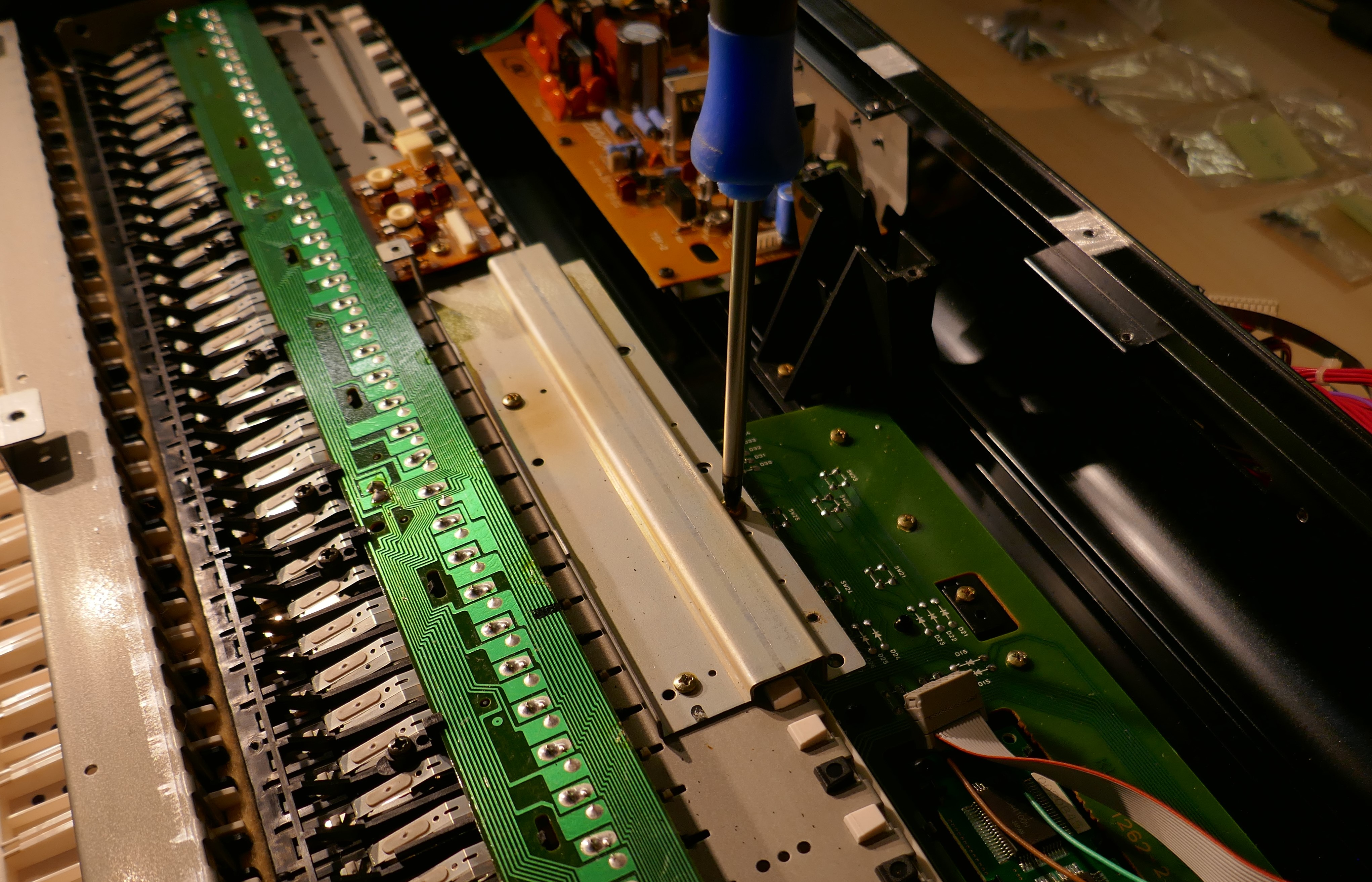
Remove the screws holding the top main boards in place.
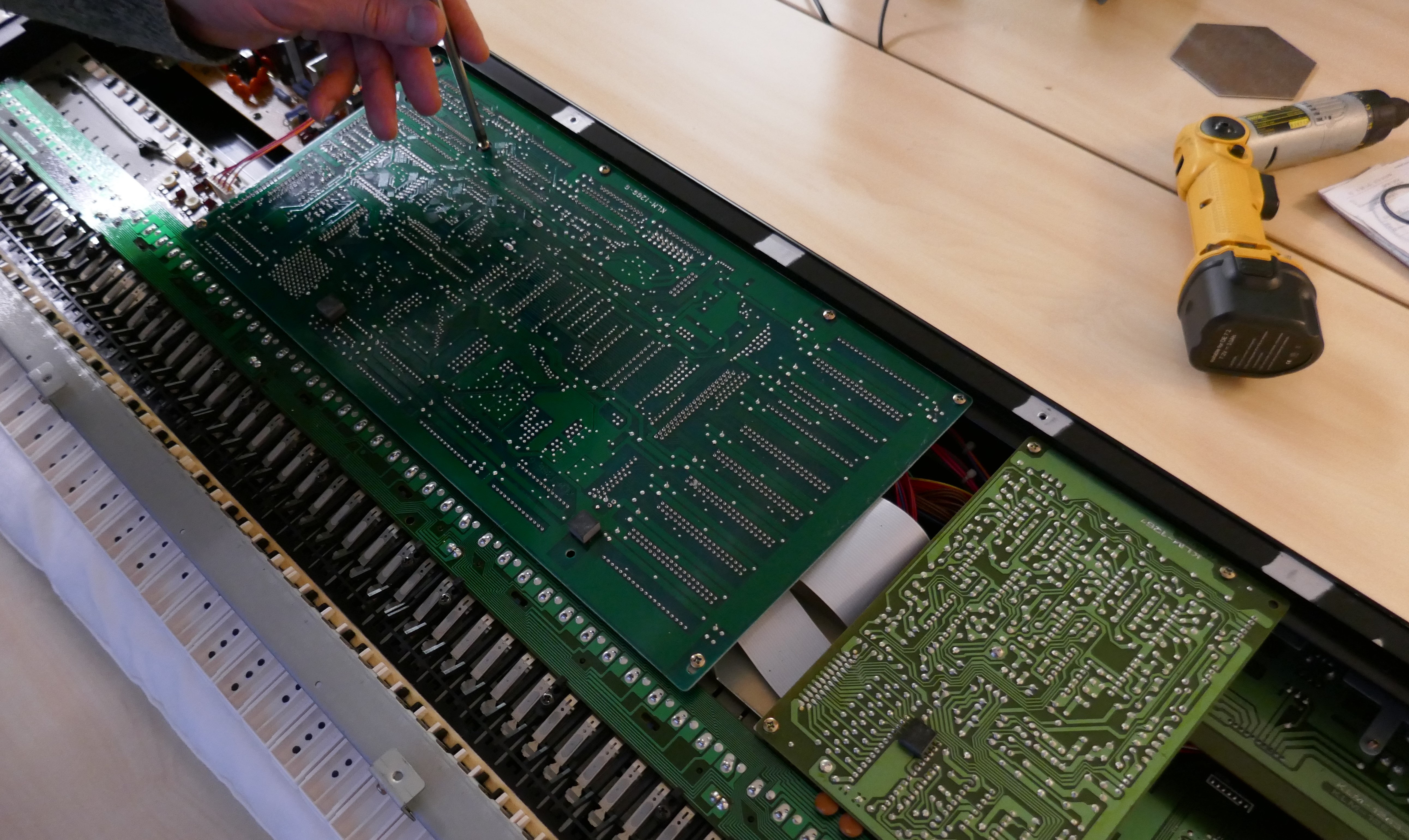
Lift out the first two PCBs, taking care with the flat cables so that they are not put under any stress. It is a good idea to unplug the display cable from the main board at this point.
For those experienced in synth repair, the new display assembly could be tested at this point, by plugging in the new assembly into the main board, making sure that all cables are connected, none of the PCBs are touching each other or any metal objects. Remember that there is mains voltages on the power supply and so there is danger of electric shock. It is a good idea to do this if you have made the display assembly yourself.
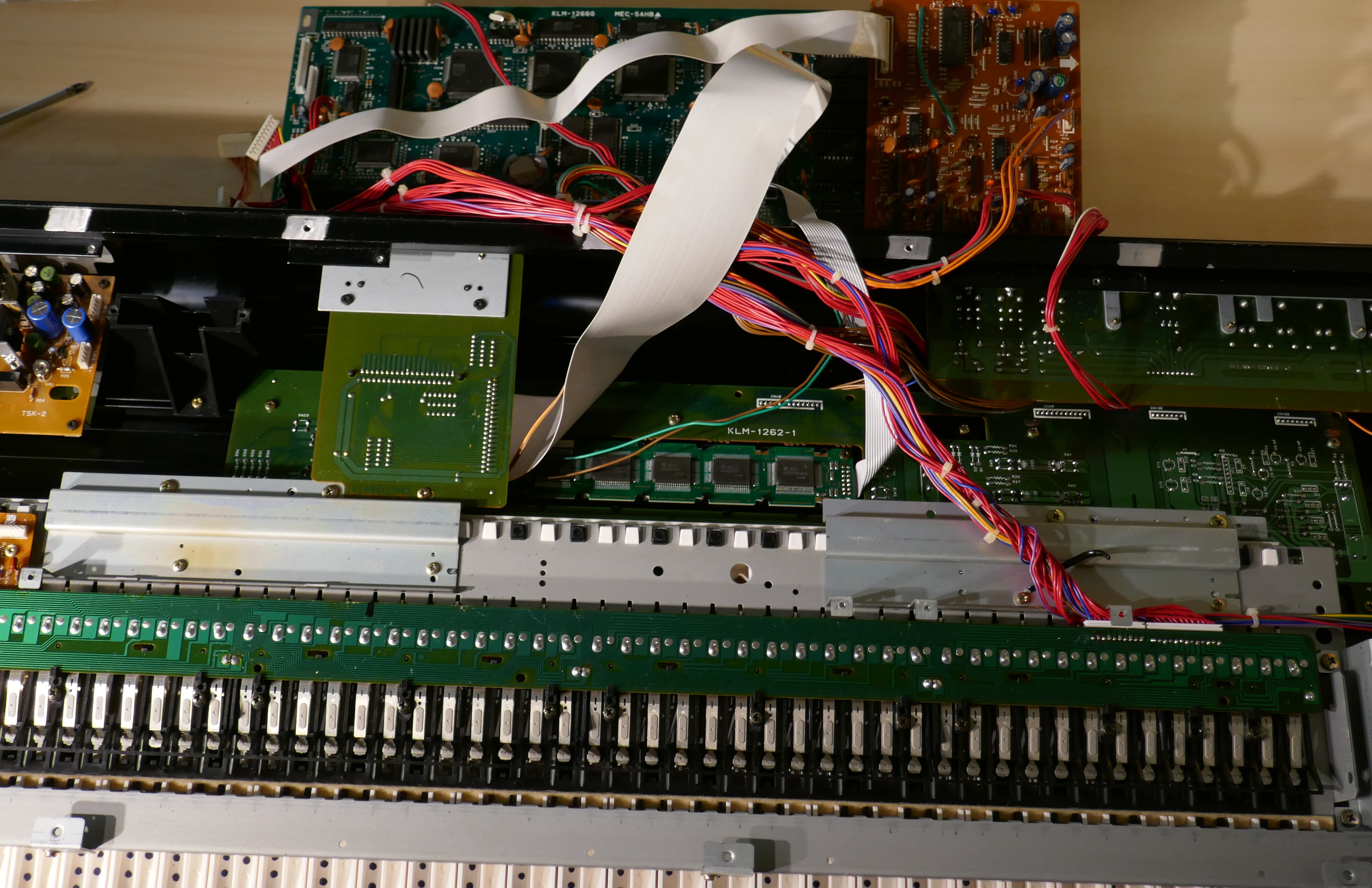
Next, remove the expansion card slot PCB by removing the screws holding it onto rear panel and internal metalwork.
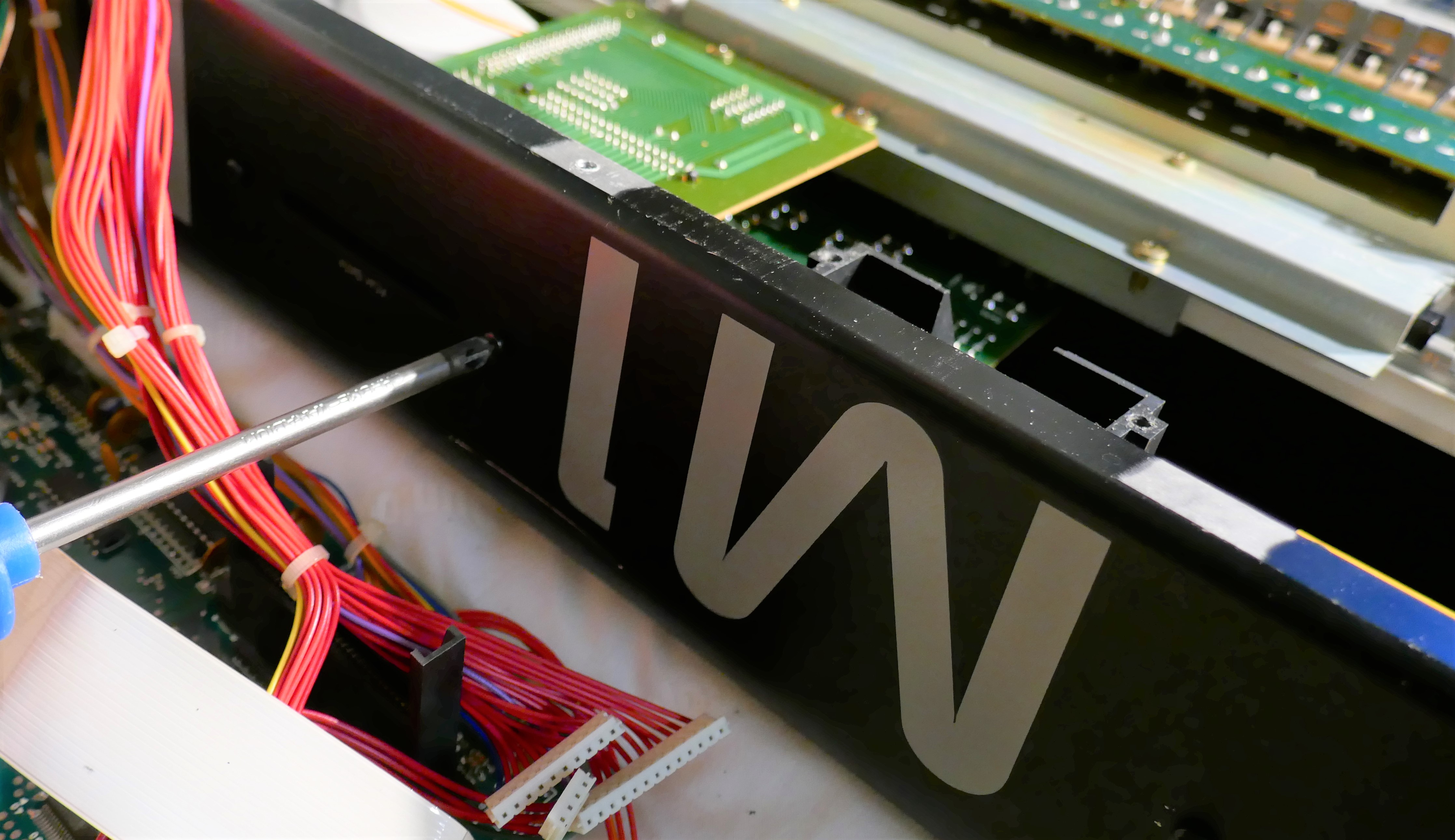
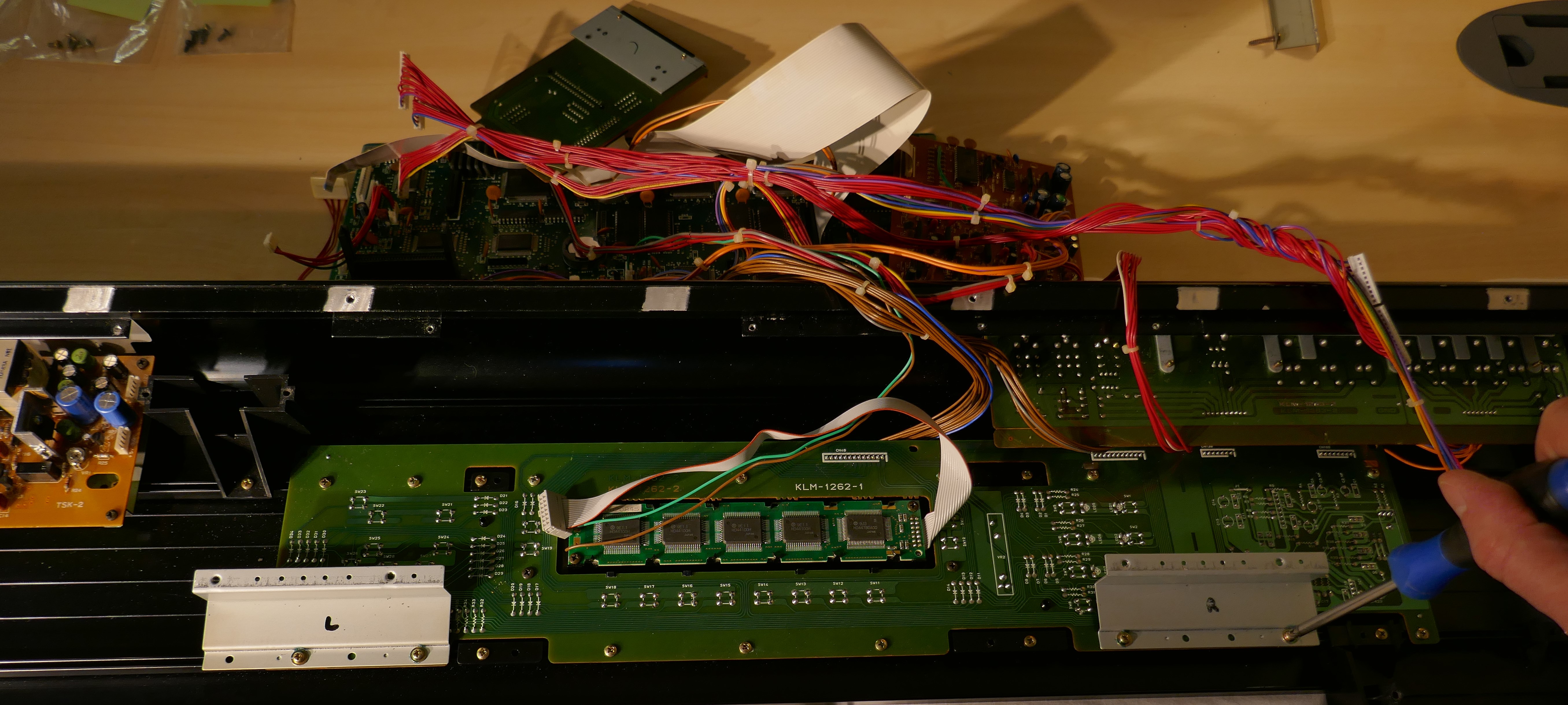
Once clear, the display can be seen in full view. It is possible to stop at this point and replace the display in situ, but unfortunately OLED panels are thinner than the old LCD back-lit counterparts, so would otherwise sit too far back behind the window. If not done already, unplug the display IDC cable from the main board.
Remove the remaining pieces of metalwork and keyboard.
Remove the switch board and display.
Mounting Pillars
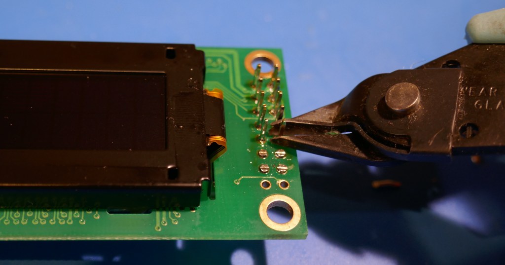
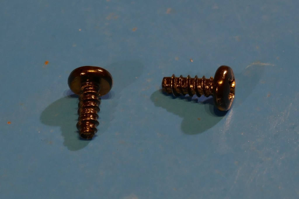
The display is secured on three existing plastic pillars. The display screws are reused as they are designed for self tapping plastic pillars. To achieve a flush display fit, it is necessary to trim the display mounting pillars to a height of 5.0mm. This can be easily achieved using a cutting tool, such as a Dremel with a plastic cutting disc/blade.
Great care must be taken, it is a tricky operation but can be tidied up with a file afterwards. Crucially, when the display mounting screws are tightened, the display frame must not be compressed hard against the panel, otherwise it will fail. If too much material has been removed, plastic washers can be used to space the display off the panel slightly. Too much material removal could result in the inability to mount the screw in the pillar.
The pictures below show the end result after trimming the pillars. Note that it is possible to remove the plastic window assembly if that makes the job easier, plus the window can re-polished more easily when separated.
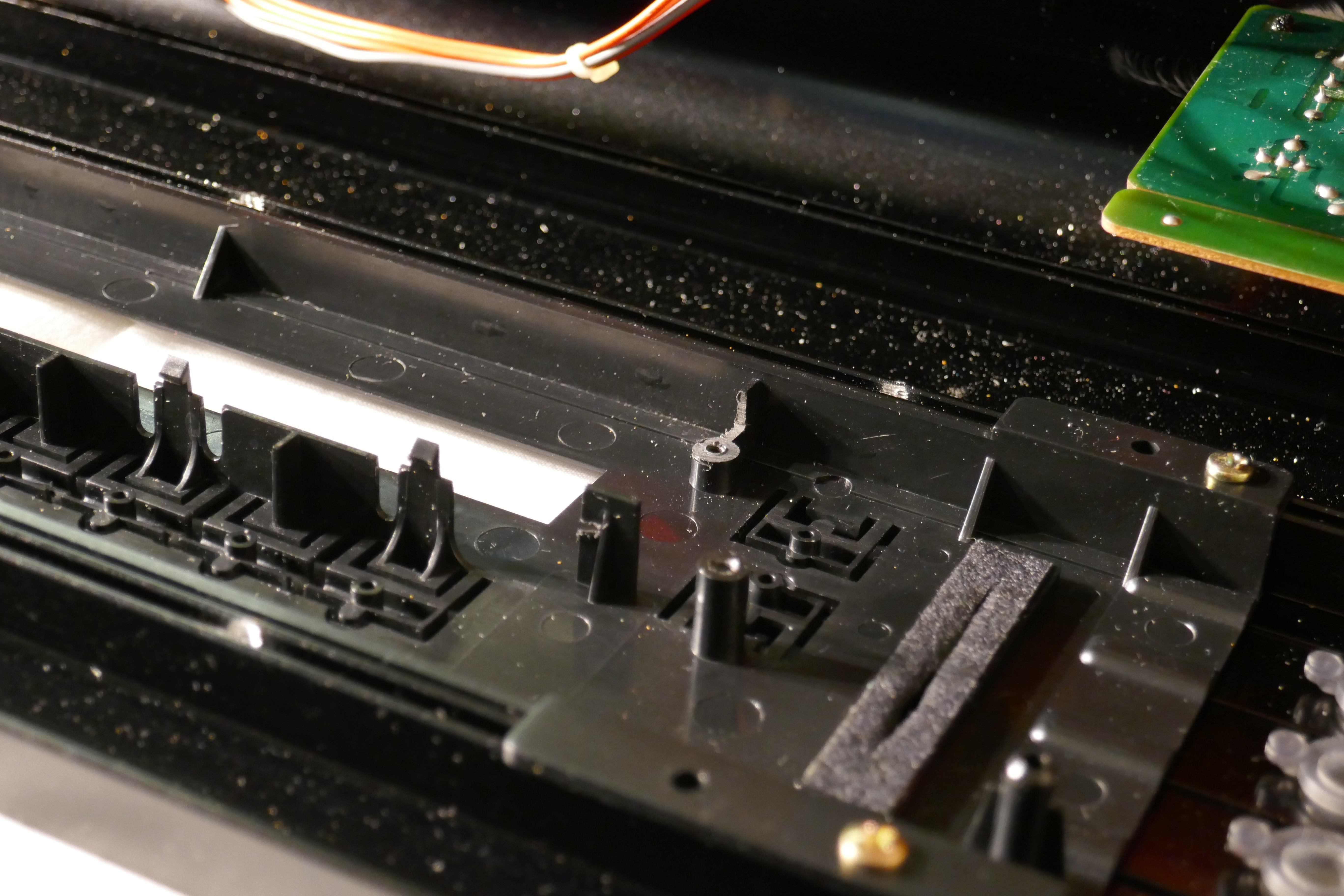
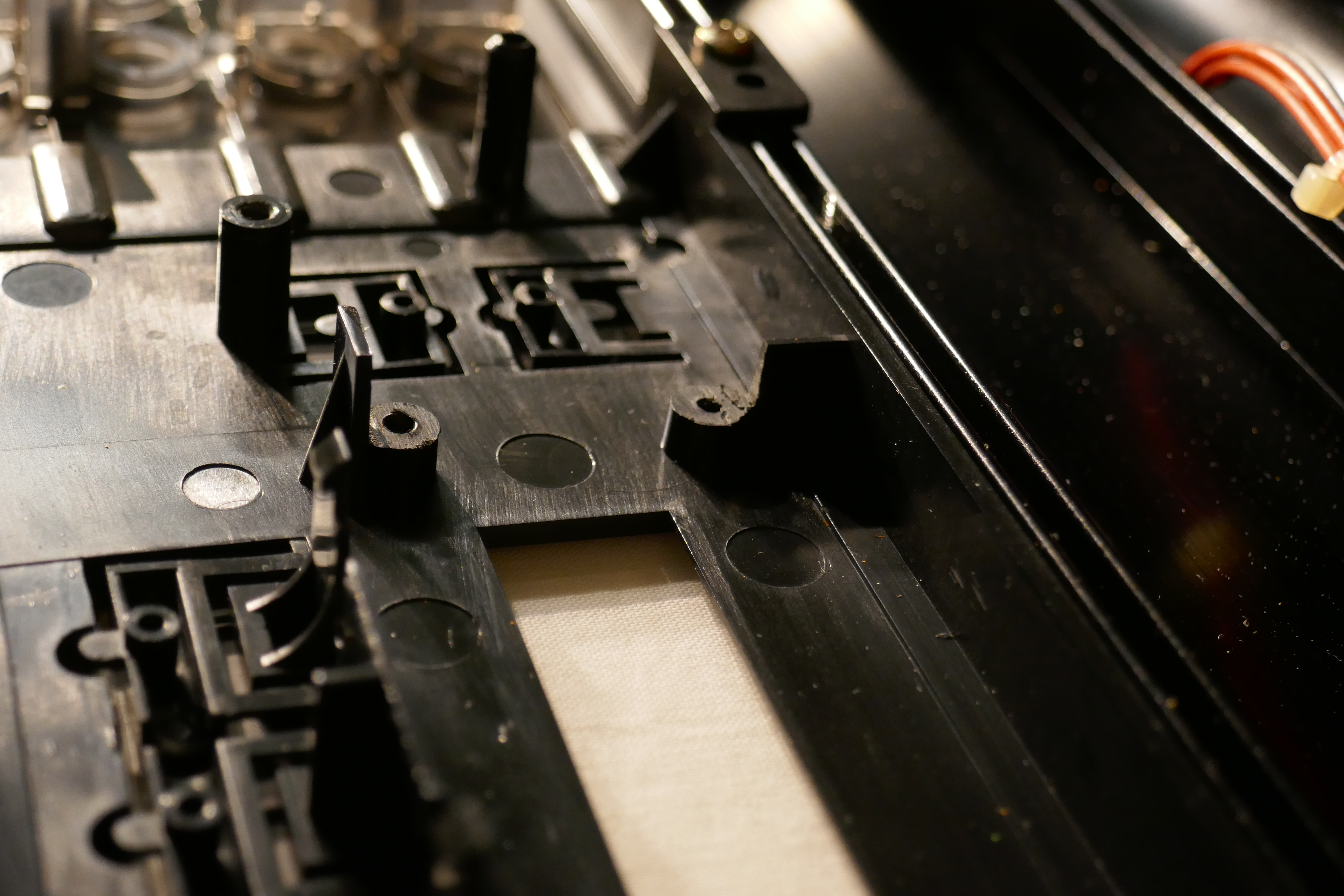
After vacuuming the debris away, using the depth gauge on a caliper, confirm the height of the trimmed pillars and try the display in position.

Display Assembly
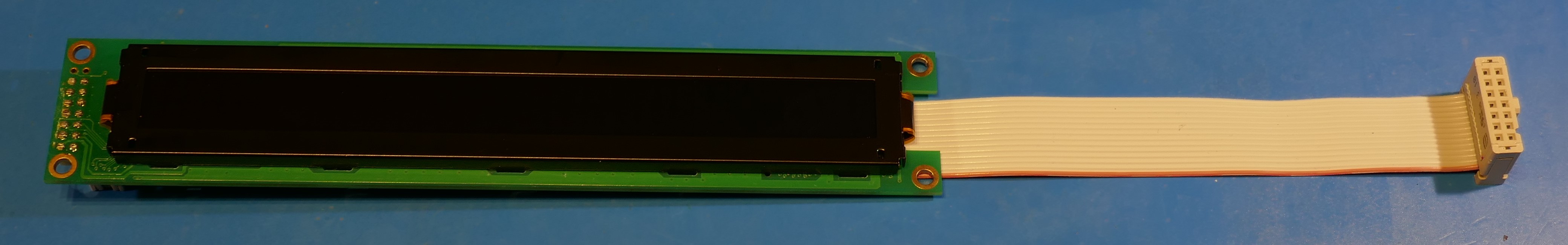
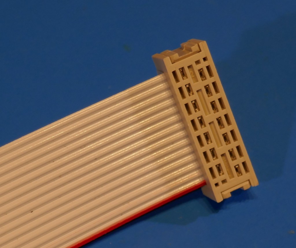
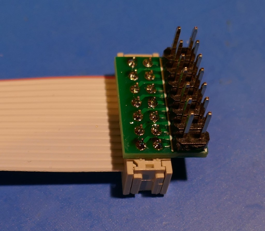
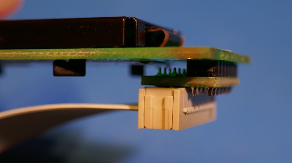
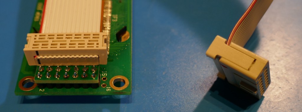
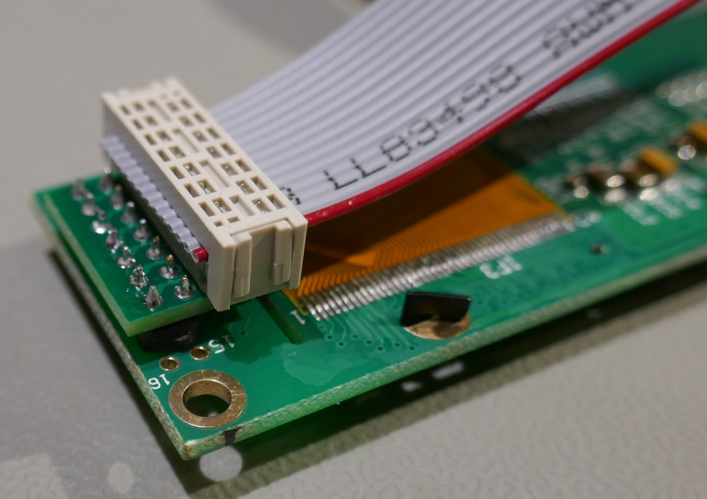
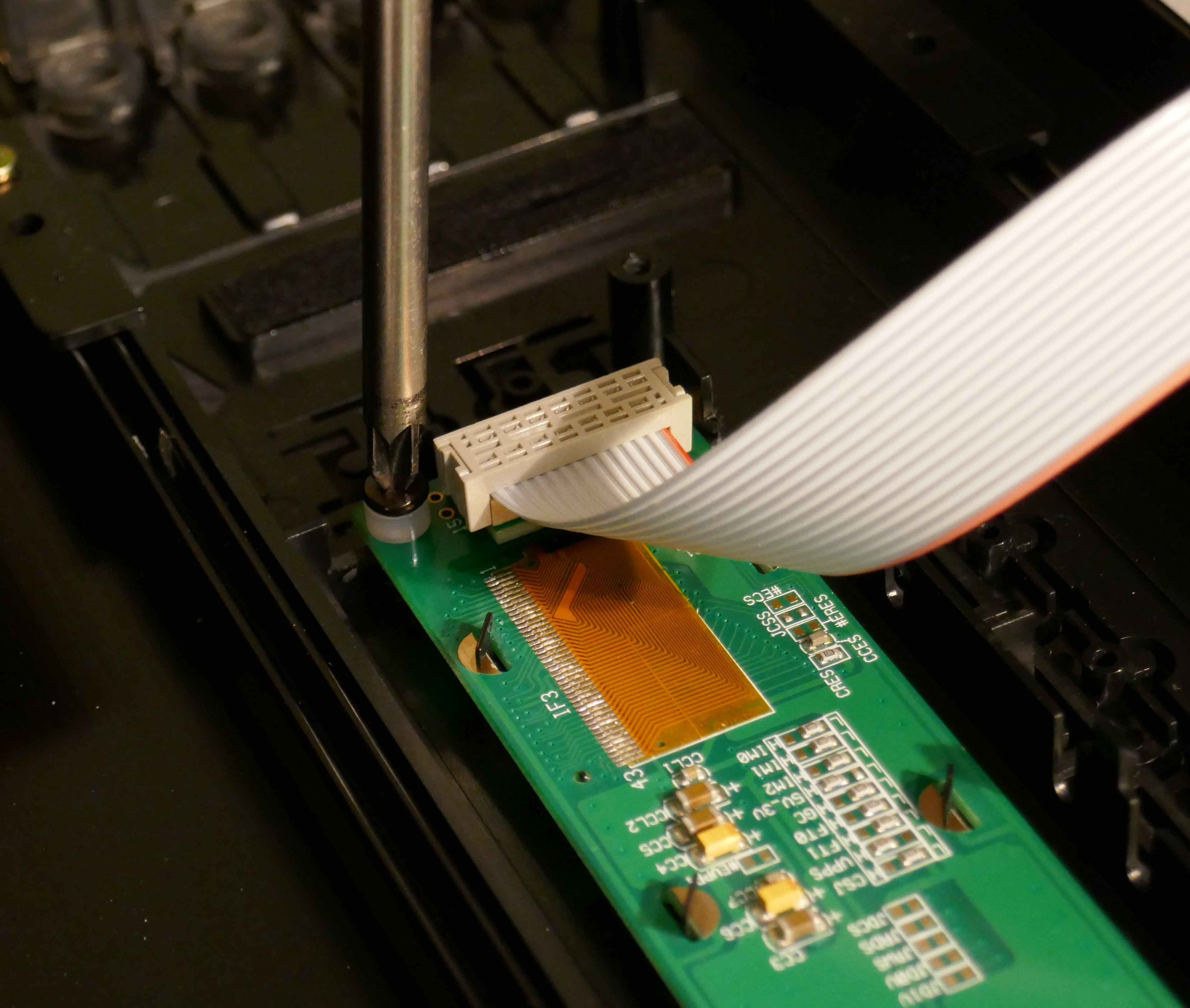
The pictures below show the replacement display module assembly. The cut piece of 14 way 0.05″ IDC cable is 31cm long. Korg designers made a cheeky design trick that can confuse the unwary: pins 1 to 14 are transposed to that labelled on a display. To correct for this, pin 1 of the cable is at pin 14/13 end of the connector.
The new OLED is too thin to be able to mount the IDC cable header to the front of the display module like the original and needs to be mounted on the rear. To transpose the connections for rear mounting, an adapter PCB is used to switch odd and even pin numbers.

Display Assembly Construction
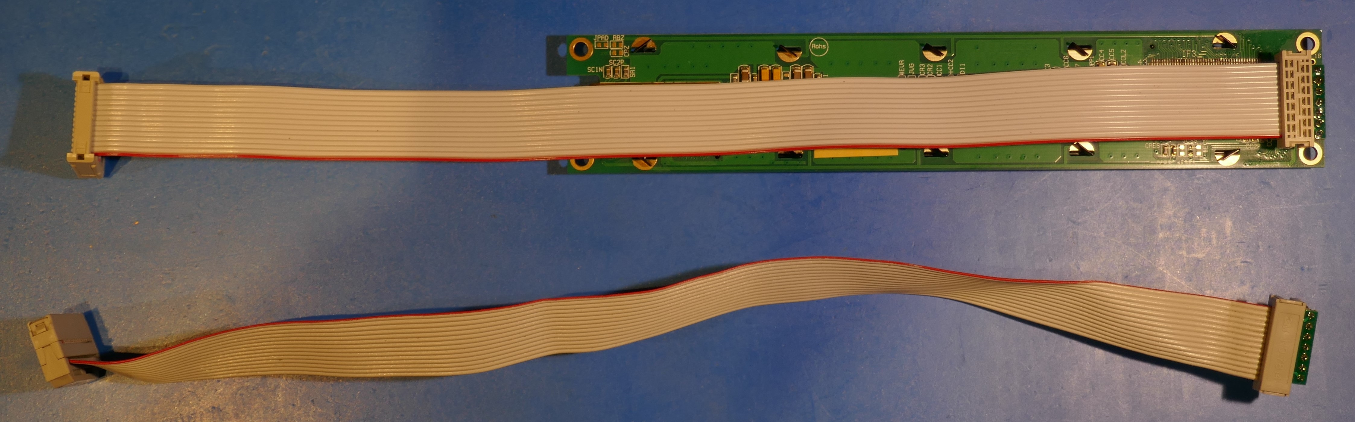
For the new Display Assembly, the pictures below show the important steps and parts needed. The piece of 14 way IDC cable is 31cm long. Pins 15 and 16 of the display are not used. Note that in the pictures the red line is in opposite position to that of the original Korg display assembly.
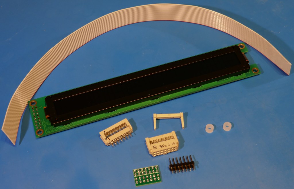

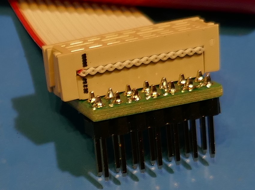
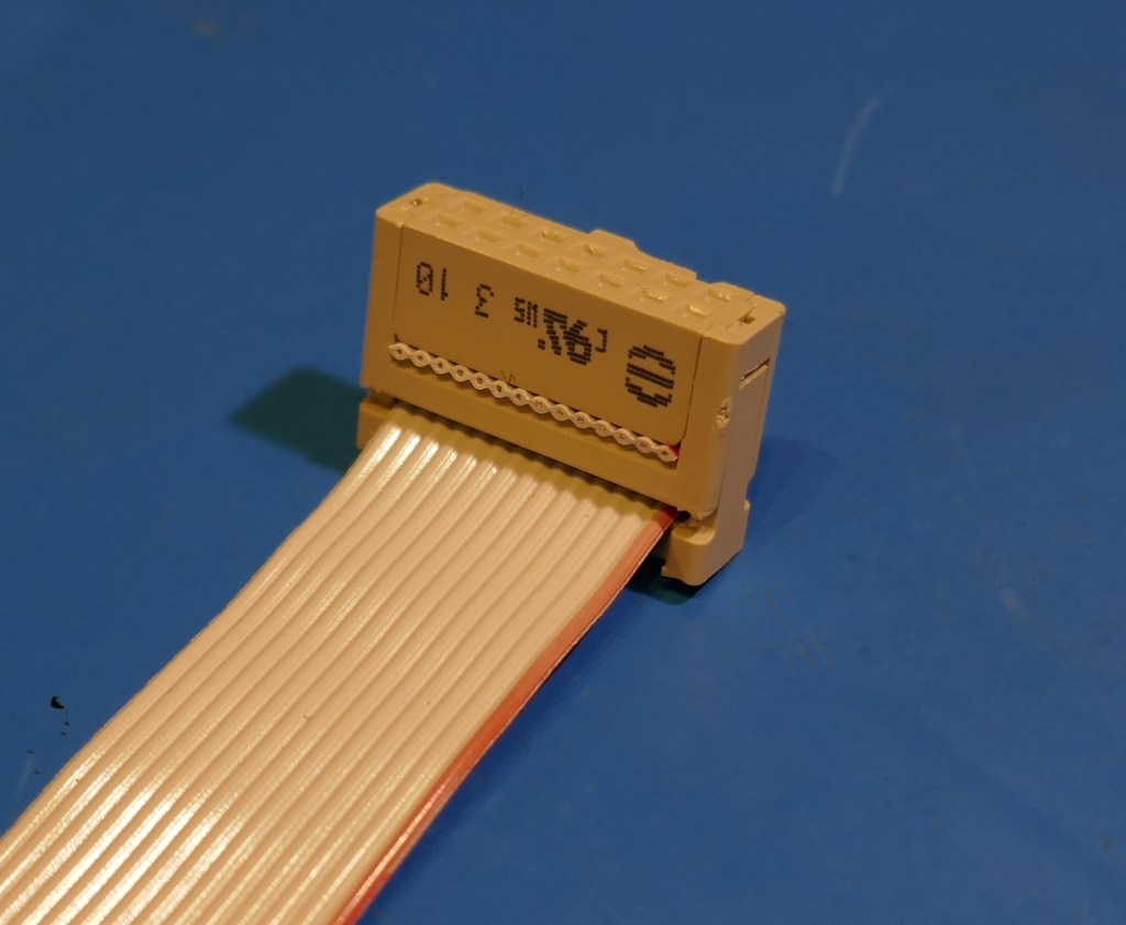
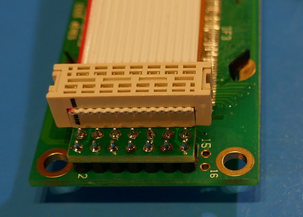
It’s much easier just to desolder the old cable and attach to the new PCB if you have an electric desoldering tool. The lower half of the picture below shows the old display cable, it’s orientation and adapter PCB attached at the end. The upper half of the picture shows the display assembly that I made with new parts so that we could sell the old display assembly.
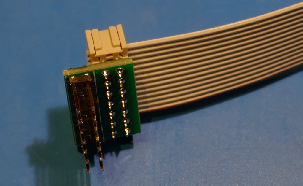
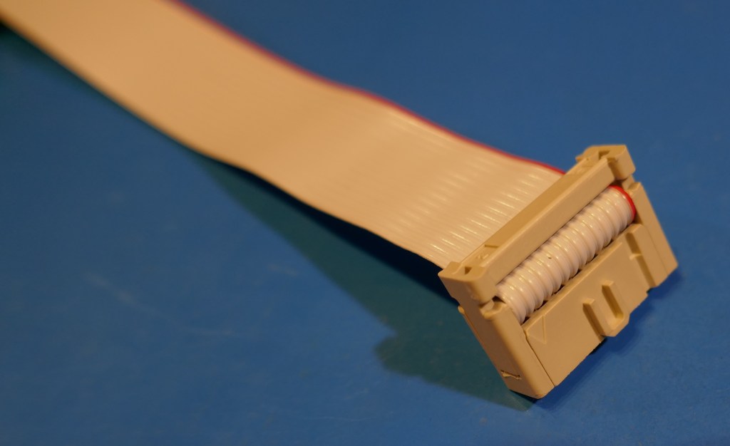
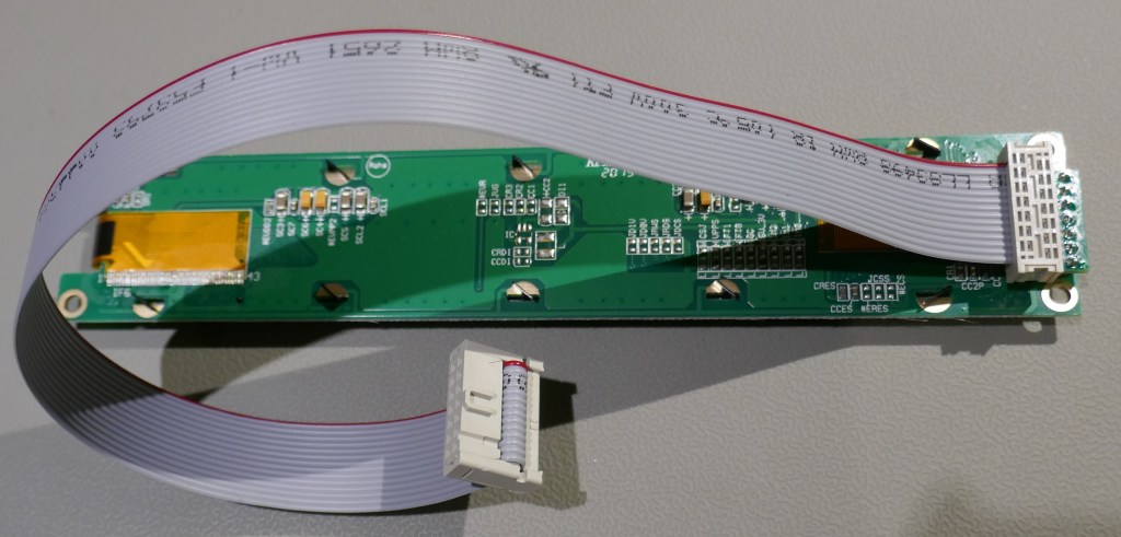
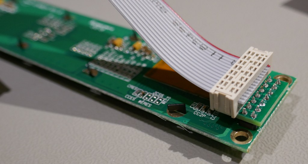
Here is a more recent picture of an assembly created in the “reflected” connection style of the original display.
Display Assembly Attachment
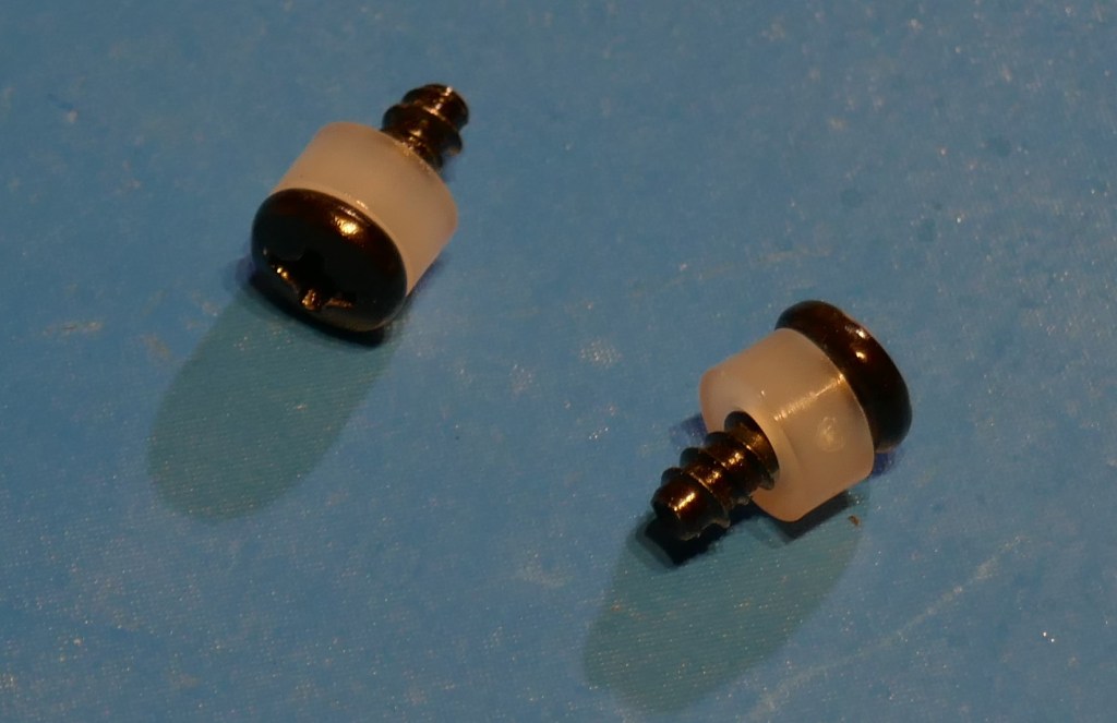
It is important to use the existing screws but is only necessary to use 2 positions to hold the display. Plastic spacers of height 3.0mm are used over the screws to take up space of the shorter pillars.
Attach the display to the panel, taking care not to over-tighten or compress the display. Also take care with the delicate flat cables that are exposed on the OLED module, see this page showing important information and care points if using our OLED modules.
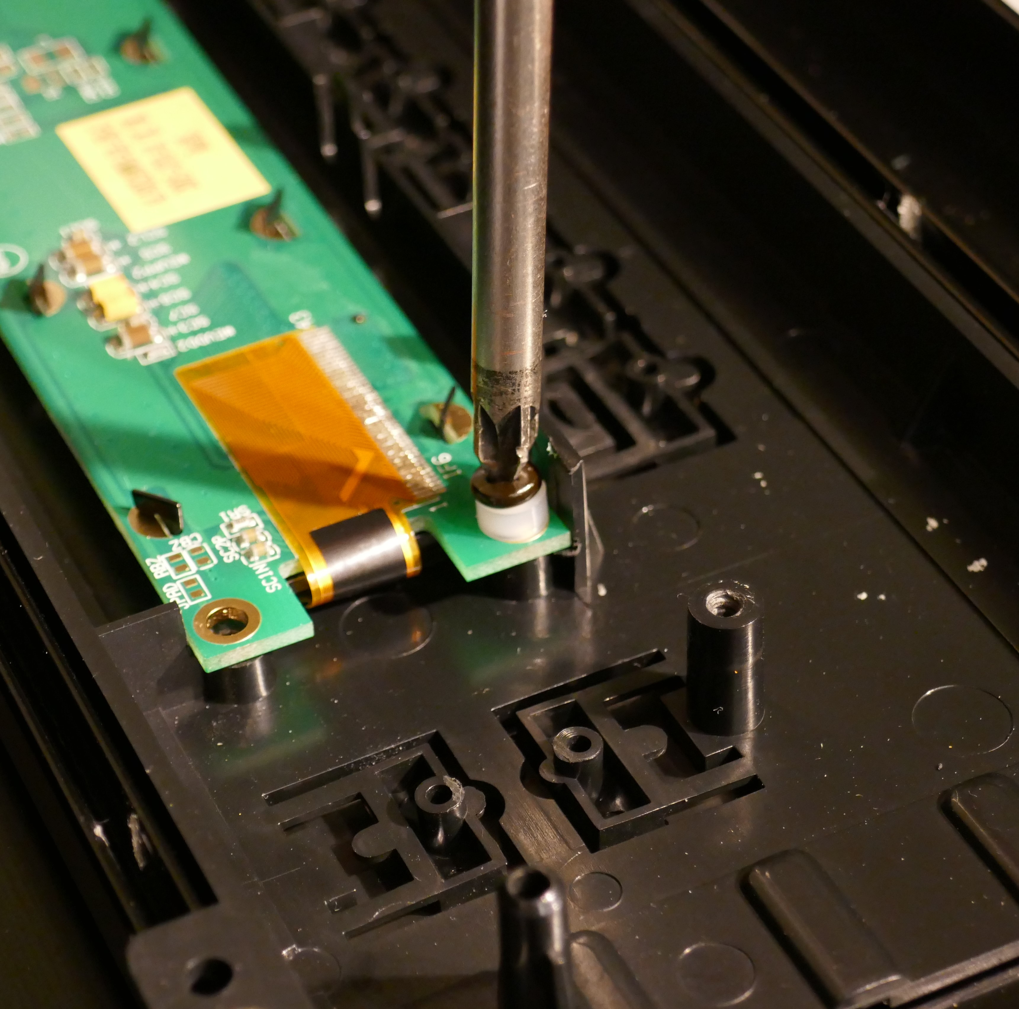
Once attached, fit the switch board back in position taking care to ensure that the buttons are sitting in correct positions before screwing the board down.
Reassemble the rest of the instrument in reverse order of disassembly and if everything went well, the display will be shown in the picture below!
Pictures taken of this display do not do it justice, brightness looks uneven in photographs. OLED is a scanned display and also confuses the camera’s white balance settings. Therefore the picture shows a blue tinge, when actually it looks white.

Super Synth Projects OLED Guide

See this page showing important information and care points if using our OLED modules.
Copyright © 2021 Super Synth Projects, Guy Wilkinson

You must be logged in to post a comment.