
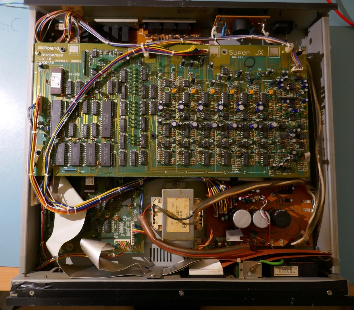
Internal View
The MKS70 is jam packed with wiring and boards, dismantling the unit can seem daunting especially the first stage of removing the Module Boards when upgrading ROMs or removing the Power Supply Board to fix dry joints or tapping off power for a new replacement VFD display.
Before You Begin
Pitfalls
There are pitfalls to watch out for:
- Weak brass standoffs that snap easily, finger tighten only!
- Weak Hot and Cold mains connections to transformer & switch.
- Cables that look very similar between top and bottom module boards.
- Flat cables that have not been refitted properly and glue on plastic backing guide has dried out
Static Electricity

When handling boards, ICs can be damaged by static electricity. Many are irreplaceable without removing one from another instrument. It is essential that ESD precautions are taken when handling these circuit boards and ground the metalwork of the instrument to earth during disassembly & reassembly.
Earthing can be achieved by connecting an audio out to a mixer or another instrument that is connected to mains earth, or simply using a piece of wire from metalwork to a nearby pipe or radiator.
When storing PCBs use anti-static packaging.
ROM Upgrade Only
If just upgrading ROMS it may be possible to do it by just hinging the boards out, however take great care and beware of the following:
- Fouling components on the module boards against the sides of the casework.
- Stressing and snapping the spacers between the module boards.
It is easier just to simply remove the Boards by unscrewing the fixings at the hinges.
Battery Change
If battery is suspected as being low on charge then check it first because removing the assigner to perform this means that most of the instrument has to be dismantled and damage to flat cables can result. See later section titled “Assigner” for how to check the battery. Even though 30 years has passed, the batteries usually do not need replacing and as current technology is “cost reduced”, they do not last as long as they used to.
Flat Cables
If the assigner has to be removed then great care must be taken to preserve the flat cables, they are vulnerable to damage. See section titled “Assigner” on this page.
Reassembly
Reassembly is simply in reverse order whilst observing the additional notes where applicable.
Re-assembly can be confusing if you didn’t make a note of where the ROMs and cables go. This guide for the noise reduction mod shows pictorially where the ROMs and cables go (see stage 2), otherwise A & B outputs could be interchanged or stereo channels swapped. See below for full configuration and explanation what all this means.
Wiring
It doesn’t matter which positions the module boards are installed in provided that the wires are placed correctly.
- The Module A board with the “B” ROM has a black wire (MIDI out) on CN1 cable pin 10 and it has Orange, Blue, Purple and Grey wires on the CN3 audio cable that end up on Jack Board CN2 pins 3,6,7,8.
- The Module B board with the “C” ROM doesn’t have a black wire on CN1 cable and it has Brown, Red, Yellow and Green wires on the CN3 cable that end up on Jack Board CN2 pins 1,2,4,5.
Wiring & ROM Position Explanation
For those of you who are curious, Upper & Lower (JX10) or A & B (MKS70) tones are controlled by software. Left and Right audio channels by wiring configuration.
The 2 voice boards are obviously identical, but only one cable has the midi out. On the software side, a board is addressed by sending a 0xF1 (LOW) or 0xF9 (UP). 0xF4 is BOTH and 0xF5 is midi-through. So to pass midi, both boards will actually forward midi, but only one is connected via the black wire on the CN1 cable.
Stereo output is dependent on order in which each voice board is connected to the two inputs on the jack board and which ROM (B or C) is installed.
Audio cables from Voice Board CN3 go to the Jack Board.
This means that you can swap the boards, but you will just get the output routed to LEFT or RIGHT audio channels, depending how the voice board output (CN3) cables are connected to the jack board.
Unplug & Remove Top Module Board
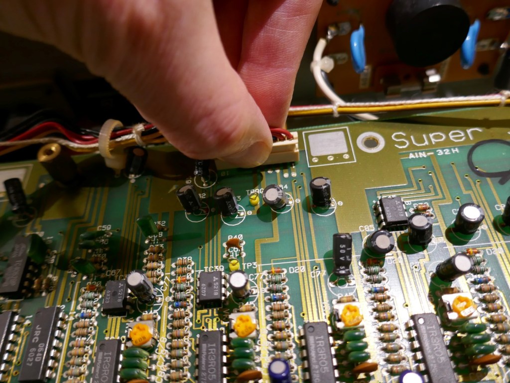
This is usually identified with voice ROM marked “C”. First unplug the cables. The left hand “control cable” near the ROM and CPU doesn’t have the black wire installed at position 10.


Next remove the screws with a suitable screwdriver bit. Many Roland synths I have looked at have had chewed screw heads because the wrong type of screwdriver has been used, this unit in the pictures is no exception.

Screws for the hinges can be easily replaced with M3 pan “cross” head. If replacing the screws it isn’t advised to use slotted ones because otherwise the risk of a screwdriver flying off and damaging circuit traces when tightening is very likely.
The Module PCBs have many integrated circuits that cannot be replaced easily because they are simply not available anymore. It is a great idea to use anti-static measures to prevent damage.
Place the module board on some anti-static surface like the blue mat in the pictures. There are easily available anti-static products like “pink bubble wrap” or “metalised bags” like in pictures below.


Unplug & Remove Bottom Module Board
This is identified with voice ROM marked “B”. First unplug the cables. The left hand “control cable” near the ROM and CPU has a black wire (MIDI out) installed at position 10.


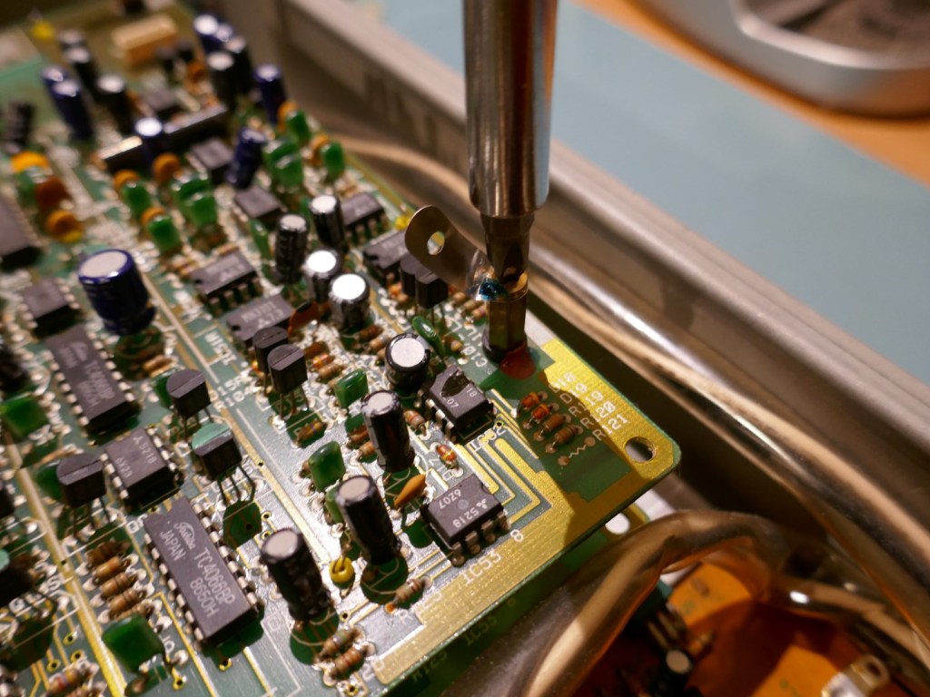
Next step is to remove the brass spacers. These are very fragile in a sense that the shafts are unable to take much torque or side loading, often these break when re-tightened or removed.
The best way to remove these is by hand.
Note that when putting back, only finger tighten and do not use any “loctite” on the thread. They wont come out because the clips and PCBs hold everything together and so they don’t need to be tight. I have seen many of these simply broken causing poor earthing or boards that wobble when the unit is transported.


Remove the module board and place on an anti-static surface or bag.
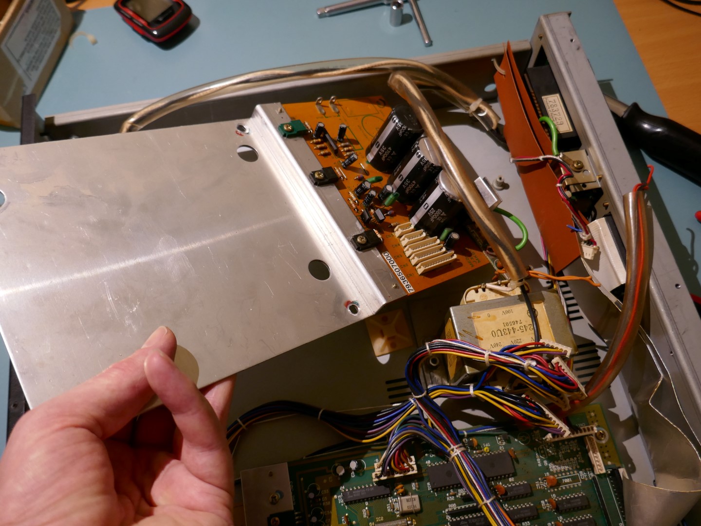
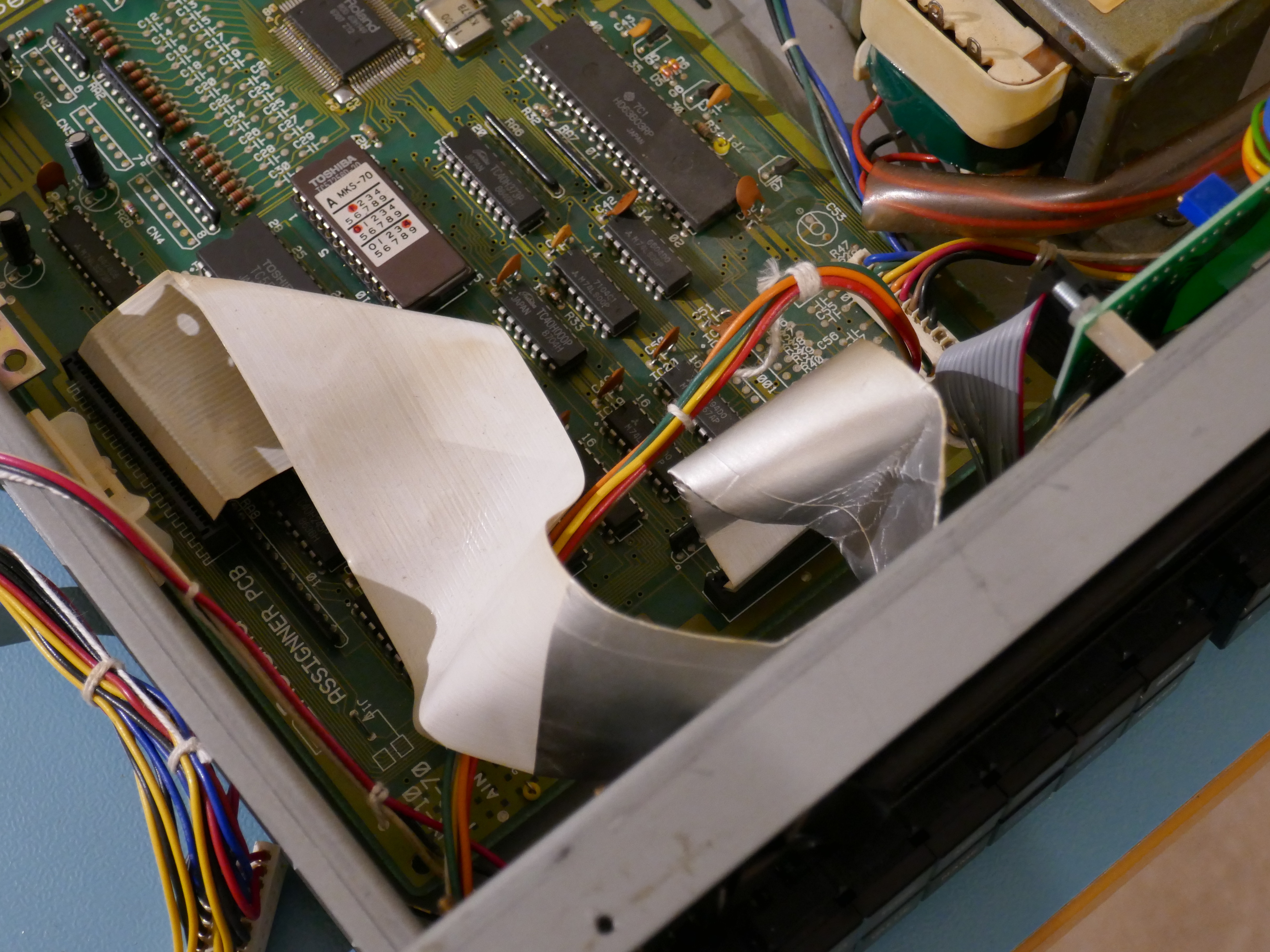
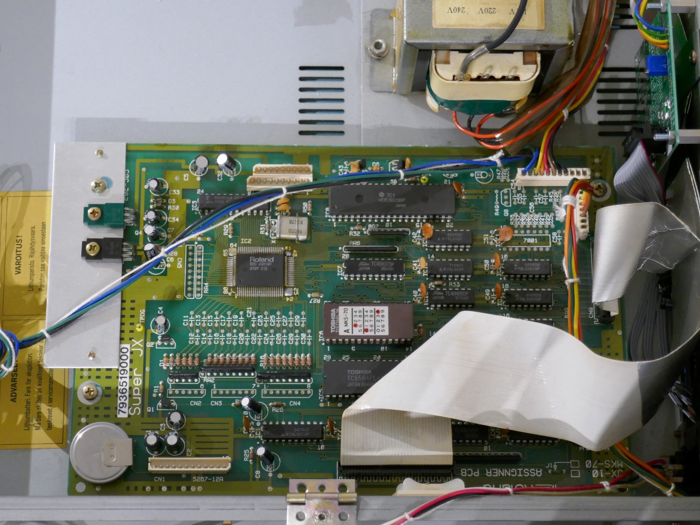
The picture below shows what it will look like with the module boards removed. This is “factory spec” wiring arrangement. Note this page showing how to rearrange the wiring to reduce noise: Roland MKS70 Noise Reduction

Power Supply Board Removal
Leaving the module board spacers in place and being careful not to knock and break them, remove the 4 bolts holding the heat-sink plate with a 7mm socket.
Note the white nylon spacers in the picture below, they are normally attached to the module board black fixing clips, in this case they have remained stuck to the spacer, so have been left in place.

Finally unplug the cables and remove the screws holding the PCB in place.


Optional Step: Disconnect Wires
If the Power Supply Board needs to be completely removed then the best way to remove the wires properly is to cut them as close to the tag terminal as possible.


When reconnecting, strip the wire back about 3mm, tin the wire with solder and attach to the tag after melting the joint. There is little point in looping the wire through the tag again, solder is enough to hold it in place. It is a good idea to apply flux to drive out impurities if the old solder is not removed from the tag.
Experts will remove the solder from the tag, remove stray wire, strip and re-loop the wire through the tag before soldering. This is ok but accessibility when the PCB is reinstalled is difficult.
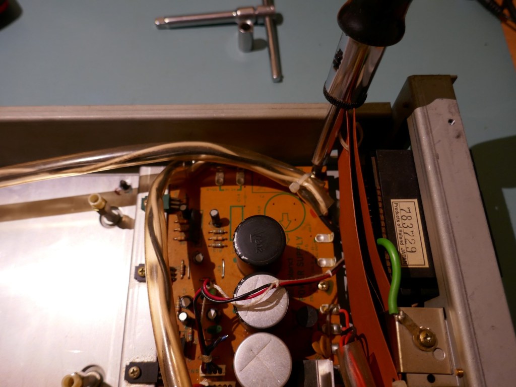
Remove the Power Supply Board
Carefully pull the board clear avoiding pulling on the white and black mains wires shown in the pictures below. The mains connections to switch and transformer tags can be weak and break easily because the interface between the wire and the solder joints is brittle due to the type of mains cable used.
If the board is not being completely removed and transformer wires are still attached, then pull partially clear and tilt to gain access to the other side. This would typically be done to correct solder joint issues or change the electrolytic capacitors.
For a method of wire reattachment, see the page SuperJX Power Supply Rebuild.
Jack Board
Like the power supply board is is usually necessary to remove the Jack Board to repair dry joints that develop over time.

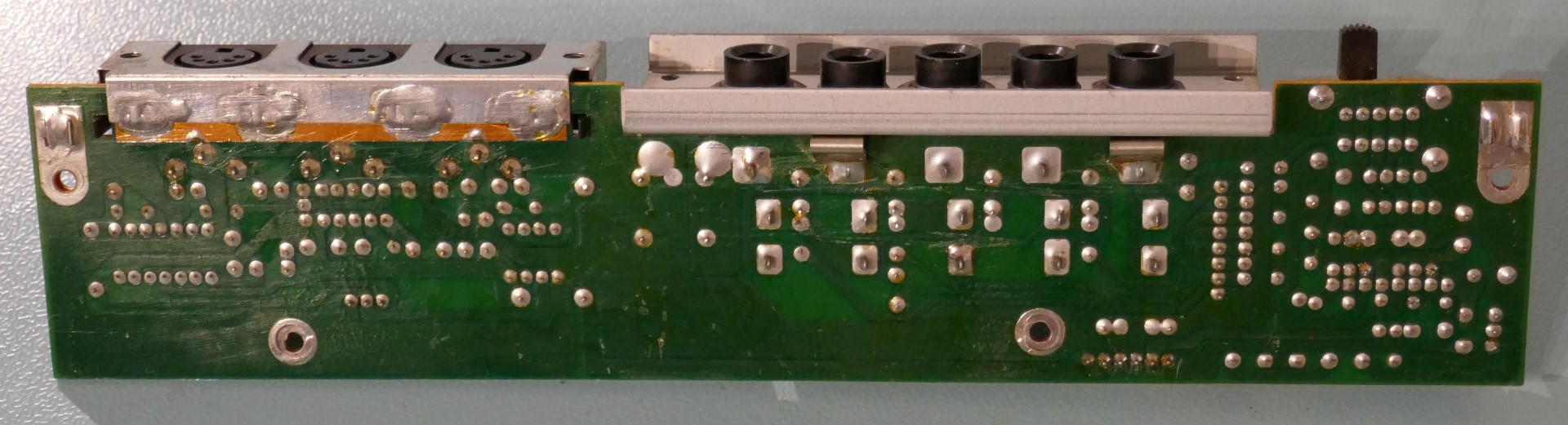
Carefully remove the cables by pulling on the connector body before removing the fixing screws. Finally remove the black self tapping connector fixing screws on the rear.


Note that the rear fixing screws are different lengths! Pull the Jack Board free.

Reassembly is done in a specific order, short black screws first followed by PCB fixing screws and long black screws.
When putting rear long black screws back in around jack sockets, DO NOT tighten otherwise the metalwork will distort. There are no spacers in between for the screws to pull against.
Assigner Removal
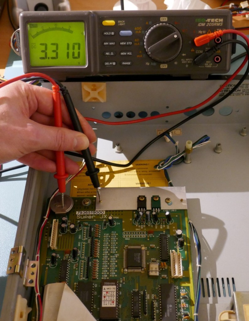
Battery Check
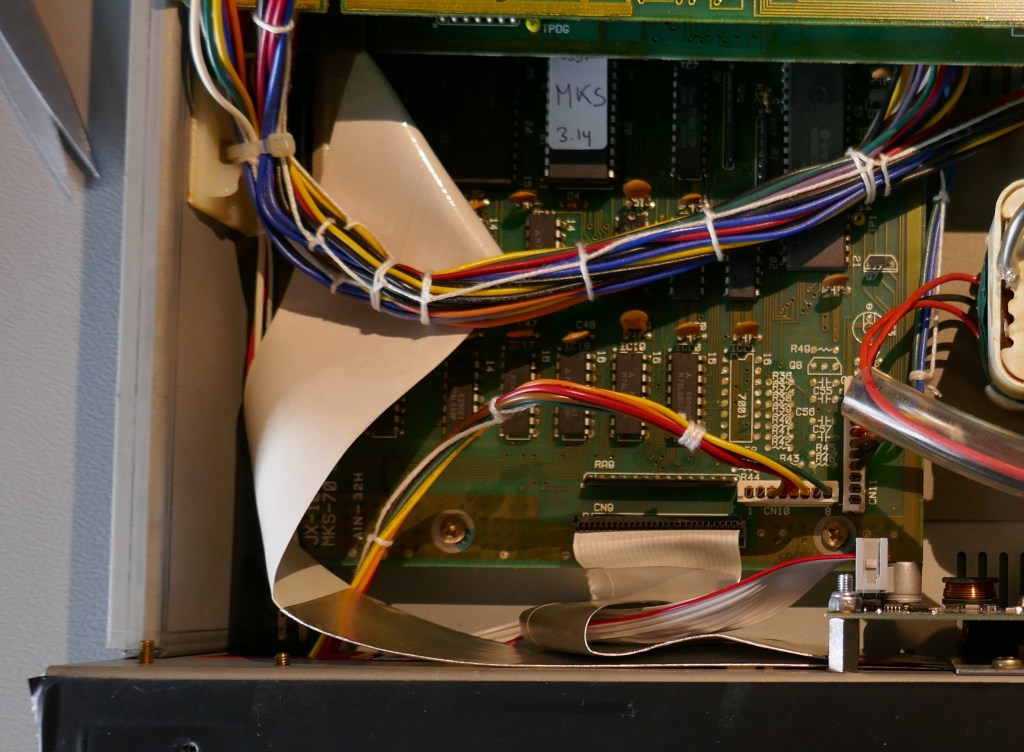
It may be necessary to change the battery however it is not worth changing if the battery is healthy. The Lithium cells used in the SuperJX were rated for extremely long life. In this example instrument, the cell still reads 3.3V and 3.0V at the RAM chip power pin. The RAM requires greater than 2.0V to hold data and therefore this battery does not need replacement.

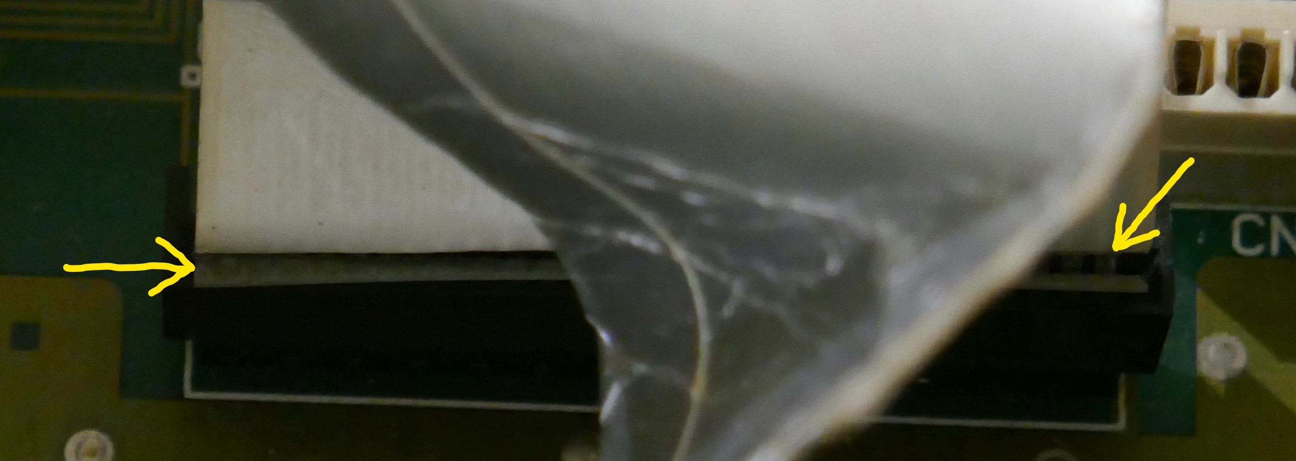
Flat Cables – Special Note
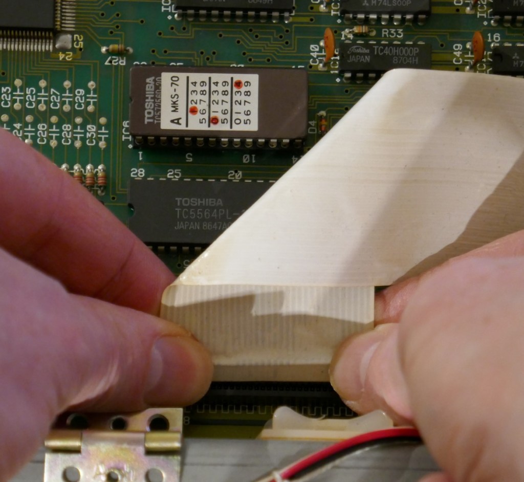
If flat cable ends show signs of the backing plastic peeling away then be aware that as soon as it is pulled, it will disintegrate. This is because the glue is no longer holding it together, the connector is instead. A cable like this once removed cannot be put back together.
The pictures below show the cartridge cable peeling away. It had been previously removed and put back in such a way that the conductors were biased with force away from the backing plastic such that the glue eventually gives way and dries up.
In this case, it is recommended NOT to remove it, unless you have a replacement.
In the picture below, this shows a classic case of butchery where the cable has not been folded back in place properly.
The pictures below show what it should look like. Roland probably liked origami.

If Happy To Remove Flat Cables
The best way to remove flat cables is to use balanced force across both sides of the cable end. These are fragile so pull on them carefully, with a constant force they do eventually slide out easily.
Note that when putting them back, make sure that the conductor side is pushed and presses against the plastic backing so that they do not separate over time.
If there are signs that this is taking place, some superglue can be employed to fix the areas that are pulling away taking care not to contaminate the conductor strips.
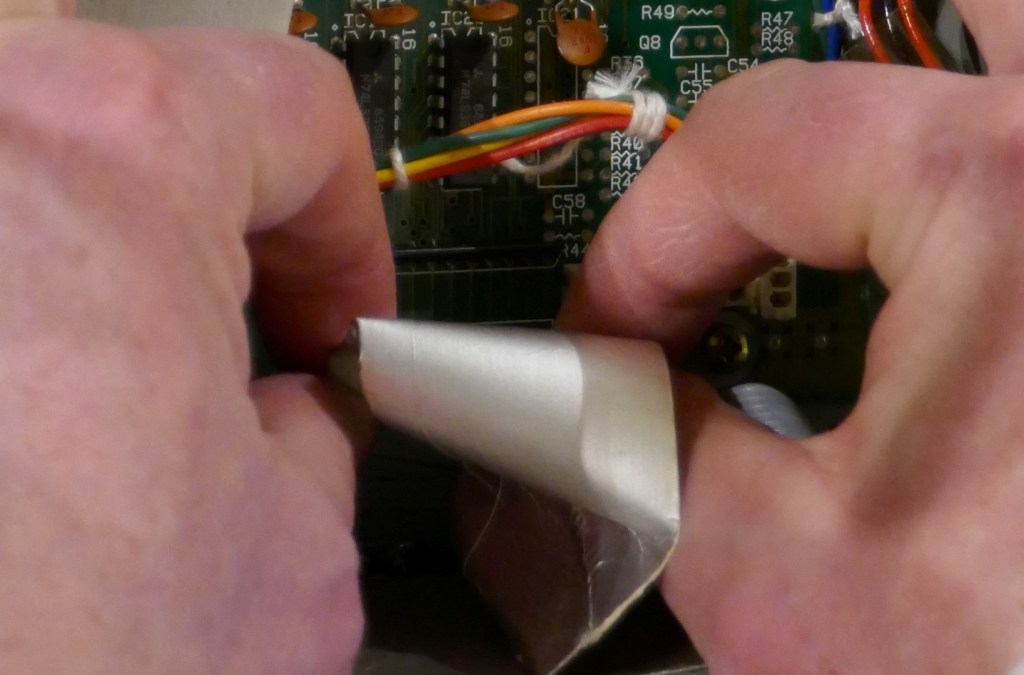
Now remove the cables by pulling on either side of the flat cable where the backing strip is.
Undo the screws holding the assigner in place and pull it free.
Copyright © 2020 Super Synth Projects, Guy Wilkinson

You must be logged in to post a comment.