The Roland JX10 has long been a favourite of mine but what started it all was seeing a JX8P in a recording studio in my teens. Once I started full time work, I went out and nearly broke myself paying for a secondhand D5. The lovely D50 was unattainable.
In recent times I have had the pleasure of revisiting my Roland LA synth days by supplying a new OLED display from my JX10 kit to a fabulous D50 belonging to a friend of mine, Jonathan Williams.
Jonathan has refurbished the instrument and knows his way around the inside, did all the hard work too.
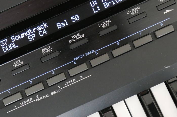
If you want one of these displays and up to the job of fitting it, I am happy to supply one. See my availability page for details. If you need a display fitting to an instrument or any other upgrade shown on this site, Plasma Music in UK offer this service.
The display used is normally supplied as part of the JX10 or JX8P kits and was specially made to order. It has a very thin construction, small dimensions and a US2011 controller. The SuperJX applications were very tricky due to space requirements, so needed these characteristics. See this guide to using our standard 40×2 OLED character module.
Looking at forums around the web, I noted that OLED displays available from well known distributors do not work with the D50 or D550. The old display has an OKI chipset so maybe some undisclosed timings were taken advantage of in the original Roland firmware.
D550
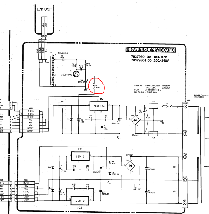
This does also work in the D550, Jamie from Toronto has written some instructions. No major modifications are necessary, apart from consider removing/disconnect L1 on the Power Supply Board. Note that Jamie did not remove L1 and found that performance was satisfactory on his machine. See D550 section for full details at bottom of this page.
Disassembly
Getting the back off revealed a display buried deep underneath nearly everything!
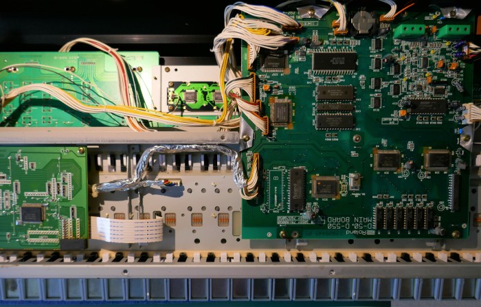
First, remove the connectors and screws around the mainboard, followed by the foil coated plastic EMC shield.
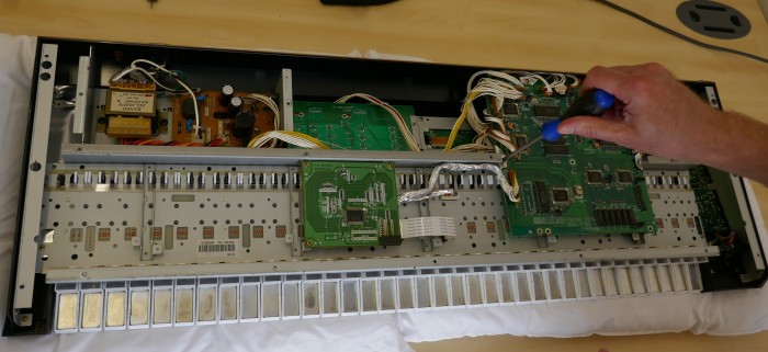
Display Removal & De-soldering
Now that the main board has been removed, the display is fully accessible from the rear. The screws that hold it in place can be undone, but be wary that the EMC choke and it’s mounting clip also need to be removed, they remain attached to the cable, are held in place with a mounting screw.
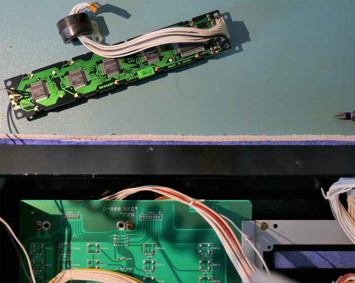
The display wires have a plastic piece that holds them in place to allow easy soldering and de-soldering. With careful attention, they can be de-soldered in one piece.

Using an electric de-soldering tool, they came out easily and whilst not letting go of the wires, the new display was put in place.
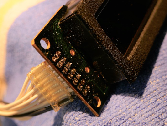
Note that connection pins 15 & 16 are not connected, just pin 1 to 14. Pins 15 & 16 are for legacy LED back light connections on older LCD, they are not used.
Leave the old backlight power leads attached to the old display and unplug from the power supply board, these are not used.
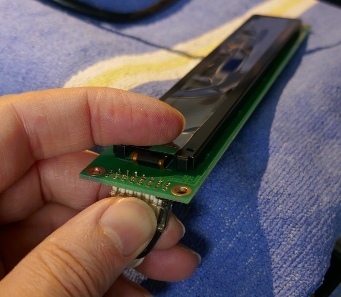
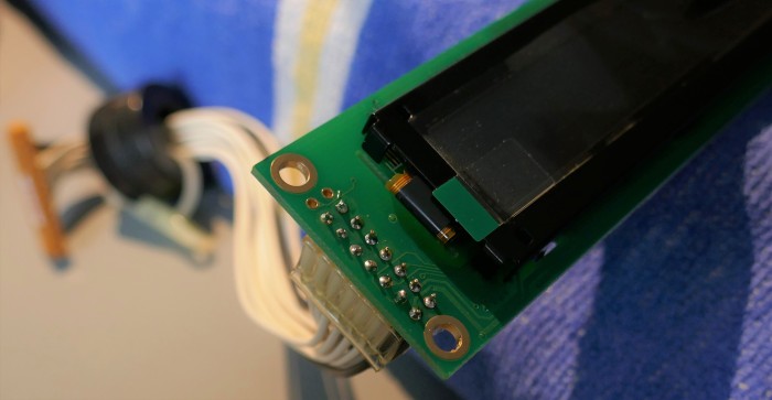
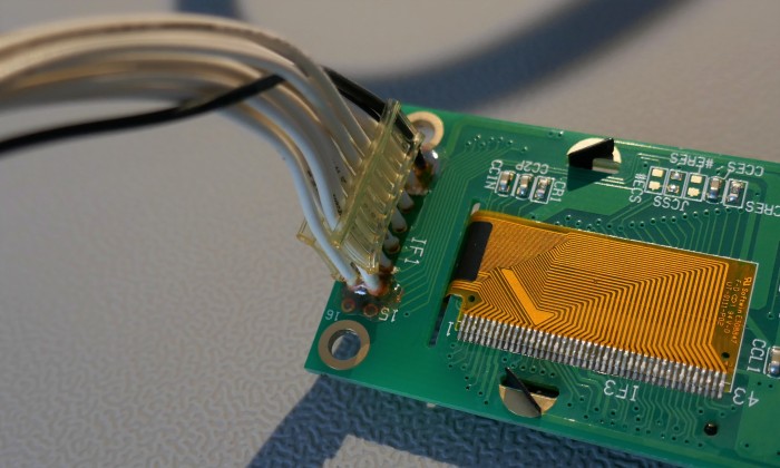
Optional Test Step
To make sure everything works before disassembly of everything else, it is a good idea to test it by reconnecting the main board to all the connections and new display.
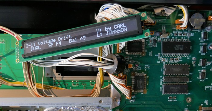
Once confirmed, switch off, unplug and remove the main board again.
Keyboard Removal
Take care removing the after-touch flat cable, it is fragile. It can tear easily if you forget and lift the keybed out whilst attached.
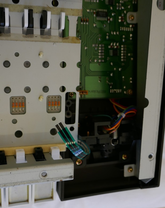
Now remove screws holding the keyboard in place.
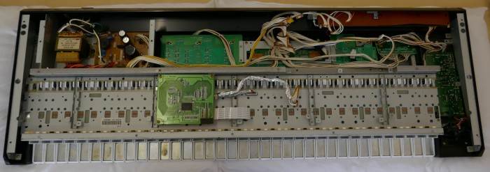
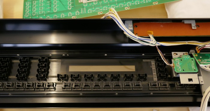
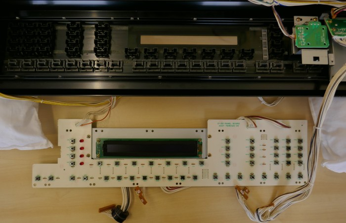
Once the keyboard is removed, the switchboard with / without display attached can be removed. This picture shows the new display in place. Note the pillows used to protect the instrument front panel, joystick and pitch bender from damage. It is essential to separate the pillows (unlike that shown in the picture below) so that they do not press on the switch caps and pop them out during switch board refitting.
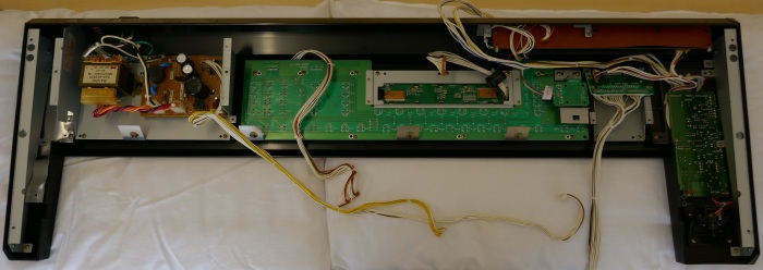
Removing the switch board reveals the plastic work underneath (with pillows separated!). When refitting the board later, if these plastic pieces are not perfectly in situ, the board will not fit.
Mounting the Display
The new display is much thinner, so has to be mounted from the font of the panel with nylon washers. A spacing of 2.35 to 2.55 mm is needed. 3 off M3 standard nylon washers were used and made for an excellent fit. Avoid fitting the OLED too close to the panel (ie. too much spacing/more washers), as crushing it will affect it’s reliability dramatically.
In this fitting, the black foam surround was reused from the old display. It had to be trimmed as the old display is not exact same size (but window is same). It is nice to have this put back as it hides gaps seen through the window.
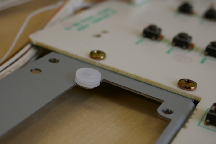
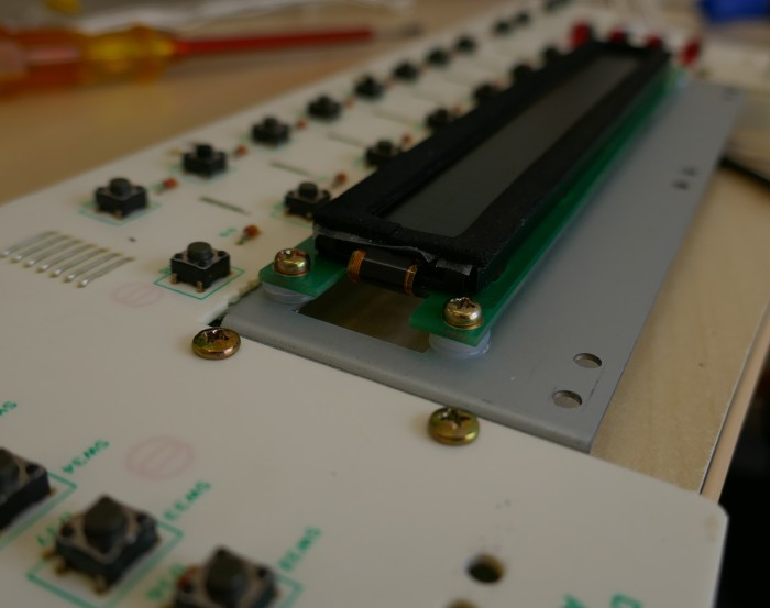
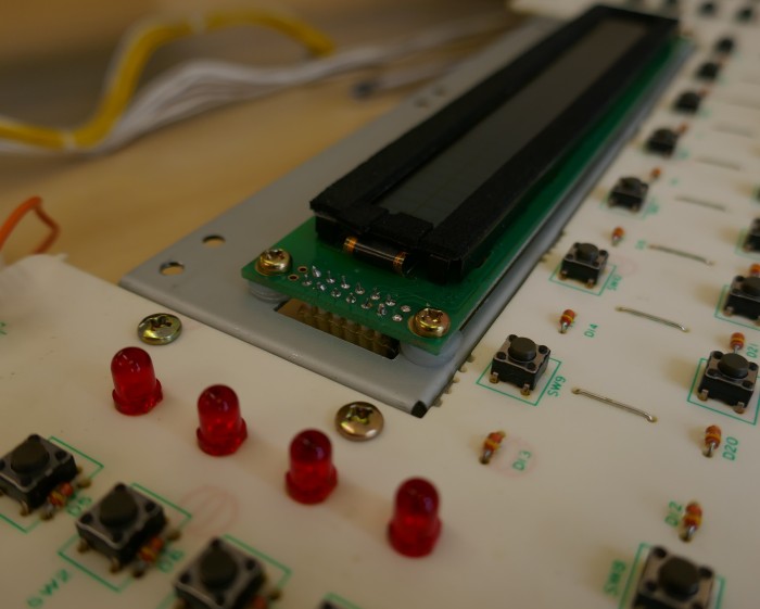
Using the existing screws, fit the new display on top of the metalwork instead of underneath. It is a good idea to bias it away from the switches if it there is slight movement.
Refitting Display Board
Display board is now fitted in place, this can be tricky because there is very little space between the plastic pieces and the display body. Luckily the dimensions of this specially ordered OLED are exceptionally small.
After practice, a technique was developed: Tilt at an angle as shown and slide back as far as possible before dropping down. It might be necessary to slide from left to right to and it should drop in place flush with the front panel.
The board should just literally drop into place, if it doesn’t, then a piece of plastic button molding has moved slightly. I tried this a lot of times with and without the new OLED to confirm it wasn’t the new display catching.
Do not force the board down, it could crack the fragile PCB (cost reduced FR2 ugghh!) or damage some plastic parts, remove and try again until it falls in place.
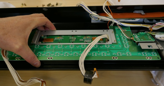
With the board back in place it should look like below. Now replace the front panel screws leaving the one that holds the EMC filter clip in place until last.
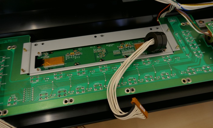
Display Attachment Detail
As can be seen, if metal washers had been used, then connections would have shorted.
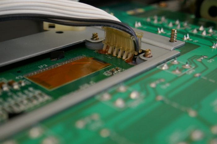
In this picture below, 4 x metal M3 washers were used and achieved the same height. They can only be used at the end without connections.
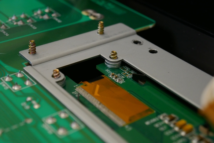
Finally, put the EMC filter back in place using a cable tie and clip. The screw self taps into the front panel.
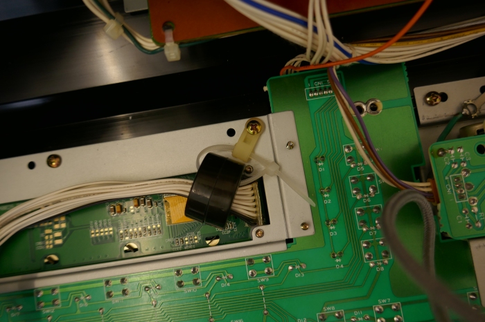
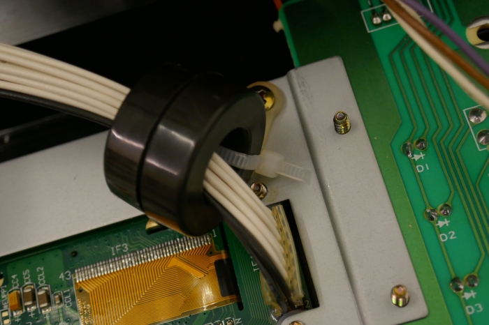
Reassembly & Test
Re-assemble the instrument in reverse order and test everything again before replacing back cover.
You now have a beautiful OLED display in your fabulous D50!
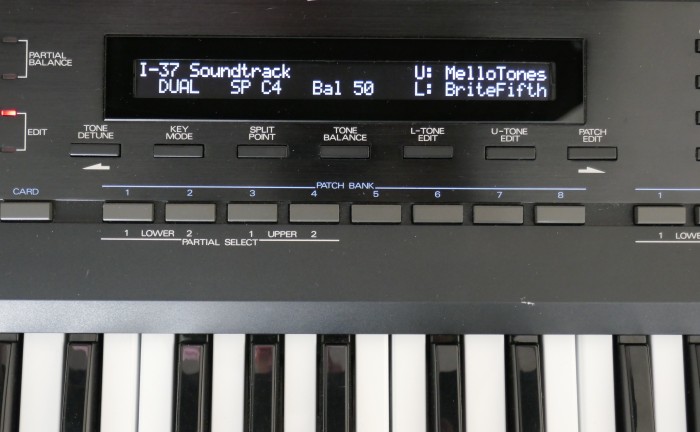
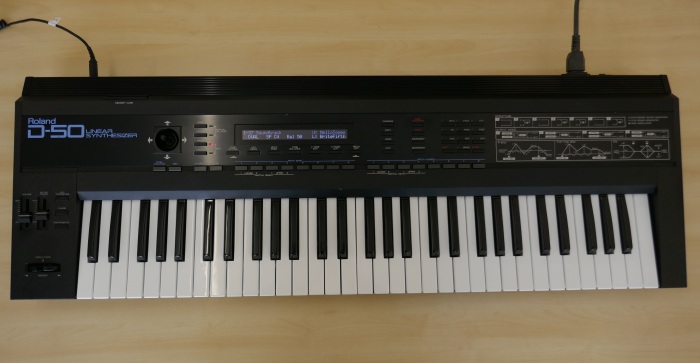
I love the D50, I want a D series again even though I grew out of the D5 very quickly…… It looks so beautiful and that patch, “Soundtrack”, is just so stunning ❤️
Roland D-550
This display is known to work and trouble free in the Roland D-550, it probably has to be attached with nylon washers on fixings near the connections to prevent risk of screw head or mounting spacers touching the power connections.
- Do not connect pins 15 and 16 on the display module.
- Do not allow the display module casing or any connection touch any metalwork to prevent a ground loop forming or power supply short.
The old display backlight is an Electro-Luminescent type and therefore the inverter ideally should be disconnected to prevent noise being generated. This is easily performed by removing L1 from the PSU once you are happy with the display working. If no noise is discovered on the audio then you may choose to leave L1 in circuit.
The inductor marked L1, circled in an excerpt of the schematic below:
Click on picture above to access the Roland Service Notes.
Jamie from Toronto wrote some instructions for fitting, they are located here:
Jamie opted to use nylon M3 screws and washers to remove all possible risk of display connections/metalwork from touching any other parts of the instrument.
Special thanks to Jamie for helping us out with this, it turned out to be a straightforward fit in the D550.
Copyright © 2022 Super Synth Projects, Guy Wilkinson & Jonathan Williams
You must be logged in to post a comment.