This DIY article shows how to replace the display in an MKS80 with a new OLED version that is visible in both day and night!

Why Did This Come About?
This design was inspired and sponsored by Peter Connelly. The MKS80 plays an important part in Peter’s professional work, take a look at his website
Many thanks to Peter for purchasing different trial displays and a donor MKS80 to sponsor this web page.
This display will also work in the Roland Alpha Juno, MKS50, S10 if firmware modification is made.
If you need this display fitting to an instrument or any other upgrade shown on this site, Plasma Music in UK offer this service.
Roland Design
The Roland MKS80 Super Jupiter Synthesizer is now showing it’s age in respect of its display. The original instrument has a 16 x 1 character LCD with Electro-Luminescent (EL) back light. The EL film has a short lifetime and the LCD sometimes fails due to corrosion between the flexible contact strip (Zebra Strip) and the PCB.
The original display is of very high quality and has an original Hitachi HD44780 driver IC, however it is rare to see a working back light after over 30 years.
Fitting a new LCD is awkward and not recommended due to the complexity of the contrast circuit in the old display and the fact that if a back-light is wanted, a new LCD with LED back light doesn’t fit due to limited depth behind the front panel.
Many users replace the back light film but again it doesn’t last and the original high voltage inverter may not be working anyway.
Replacing a display can be tricky because of shortcuts made by Roland engineers relying on some aspects of the HD44780 driver IC that are not replicated in modern devices.
If looking at different display brands, compatibility is fraught with difficulty, for example, avoid displays using a US2011 controller. The MKS80 firmware respects the timings but does not send all of the right commands.
Luckily an OLED is available from Winstar that is electronically compatible and physically fits. OLED doesn’t need the contrast circuit or inverter to function either. Better still, the old noisy inverter circuit can be disconnected. No firmware mod is required.
Winstar Part Numbers: WEH001601BWPP5N00000 (White), WEH001601BBPP5N00000 (Blue)
Other displays are possible, see connection recommendatiosn below: MIDAS Part Number: MCOB11605AV-EWP (white) or MCOB11605AV-EBP (blue). Vishay Part Number: O016N001AGPP5N0000 (green)
Vishay & Midas displays have been made obsolete and so in short supply. Winstar displays are in production for bulk order but not generally available in distribution.
Yellow Display on an MKS80?!
On Forums, many assume that yellow display might not look good. Not only is it brighter it looks fabulous, especially as the tune knob is yellow. Yellow is also sometimes available.

Caution! Vintage Electronics
In these pictures you may notice the blue mat. This is to keep static electricity under control.

Anti-static mats and wrist bands can be purchased from eBay for very little money. Many electronic parts in the MKS80 are no longer available, taking anti-static precautions reduces the possibility of damage or weakening of old semiconductors.
Mistakes, everyone makes them but check your work carefully. Although it can be boring, the issue with old technology is that parts are hard to find and circuits have little or no protection.
OLED displays are sensitive! Use ESD protection, or long term reliability will be affected.
Display Removal
Remove the rack ears, lid and front panel. Sadly the old LCD is not attached with a connector but a wire to solder crimp connection.
It is best to de-solder the LCD in situ, whilst it is held by the four mounting screws. It is best done with an electric de-soldering pump tool because the connector has spring loaded pins that grip to the sides of the plated through holes.
This example was done using a hand de-solder pump with a few attempts per joint and using fine nosed pliers to “wiggle” the pins away from the sides of the pad and hole.
It is a good idea to protect the front panel buttons from solder splashes and potential damage by a misplaced iron before undertaking any work. Buttons are irreplaceable!

Once the solder has been removed, remove 4 screws that hold the display before the wire to board connector is teased from the old display. A hot iron may need to be applied to encourage each pin to fall out, maybe in some cases, pinching the pin ends with pliers to make them narrower and detach more easily.
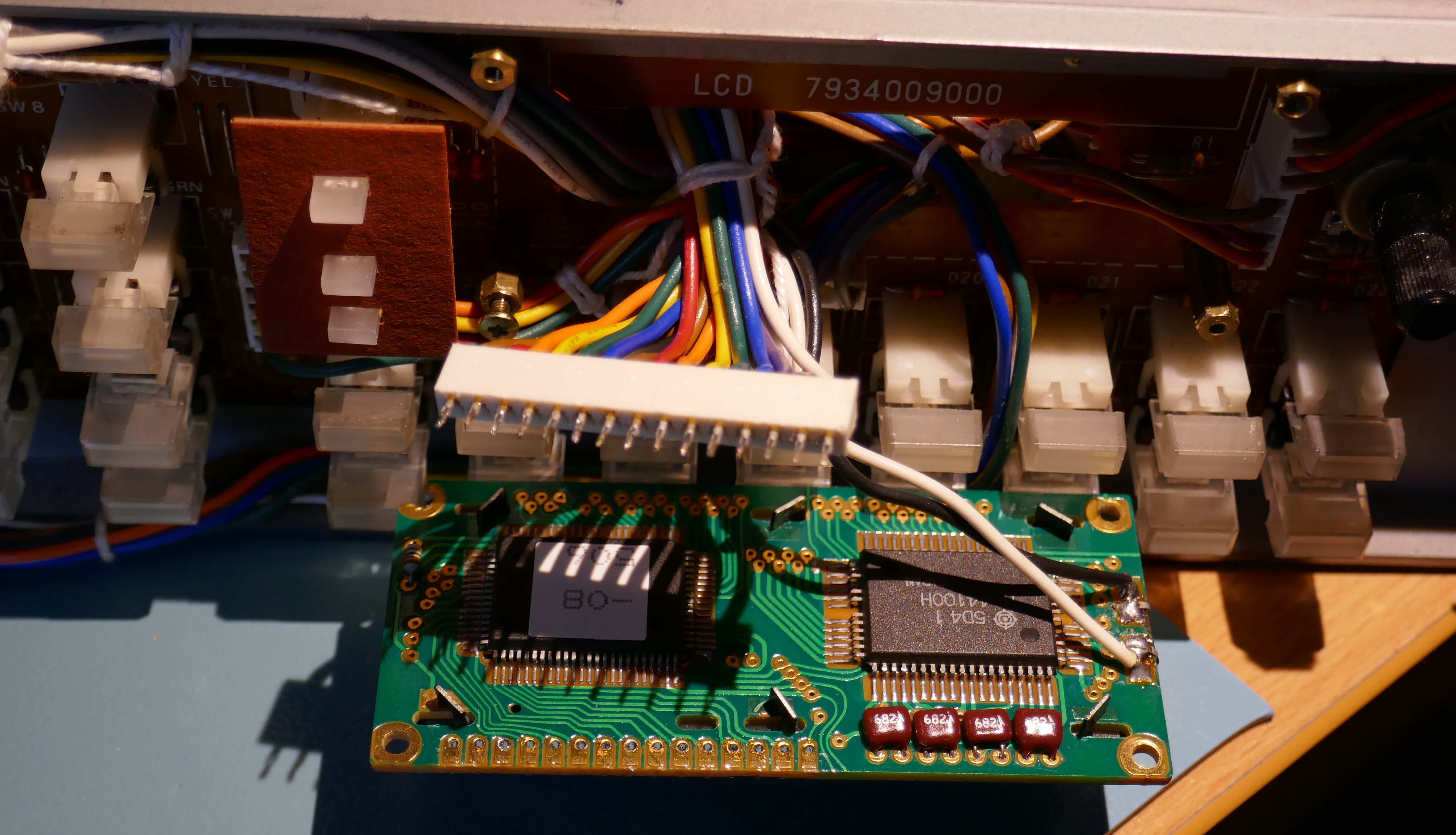
At this point I nearly lost my patience and simply cut and attached the wires directly to the OLED display. However, more teasing, re-soldering and de-soldering it eventually came free. The close up shot below, shows how the pins are constructed, they are not solid but formed and spring loaded, hence the difficulty in removing them using basic soldering tools.
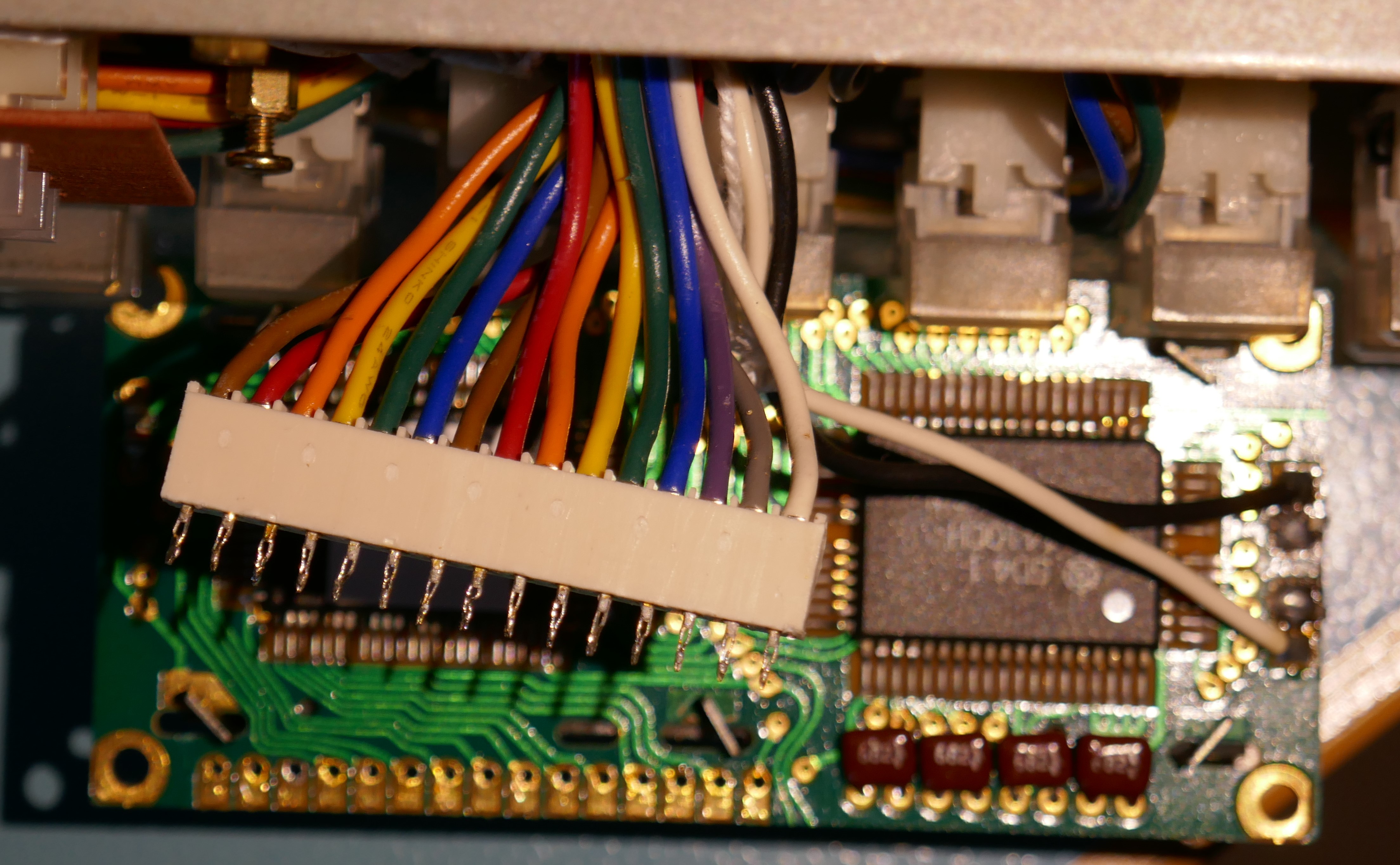
Unplug the EL back light connector (white & black) wires from the assigner board and pull the LCD free.

OLED Display Fitting
The new OLED can now be placed in position and mounted on the 4 existing pillars.
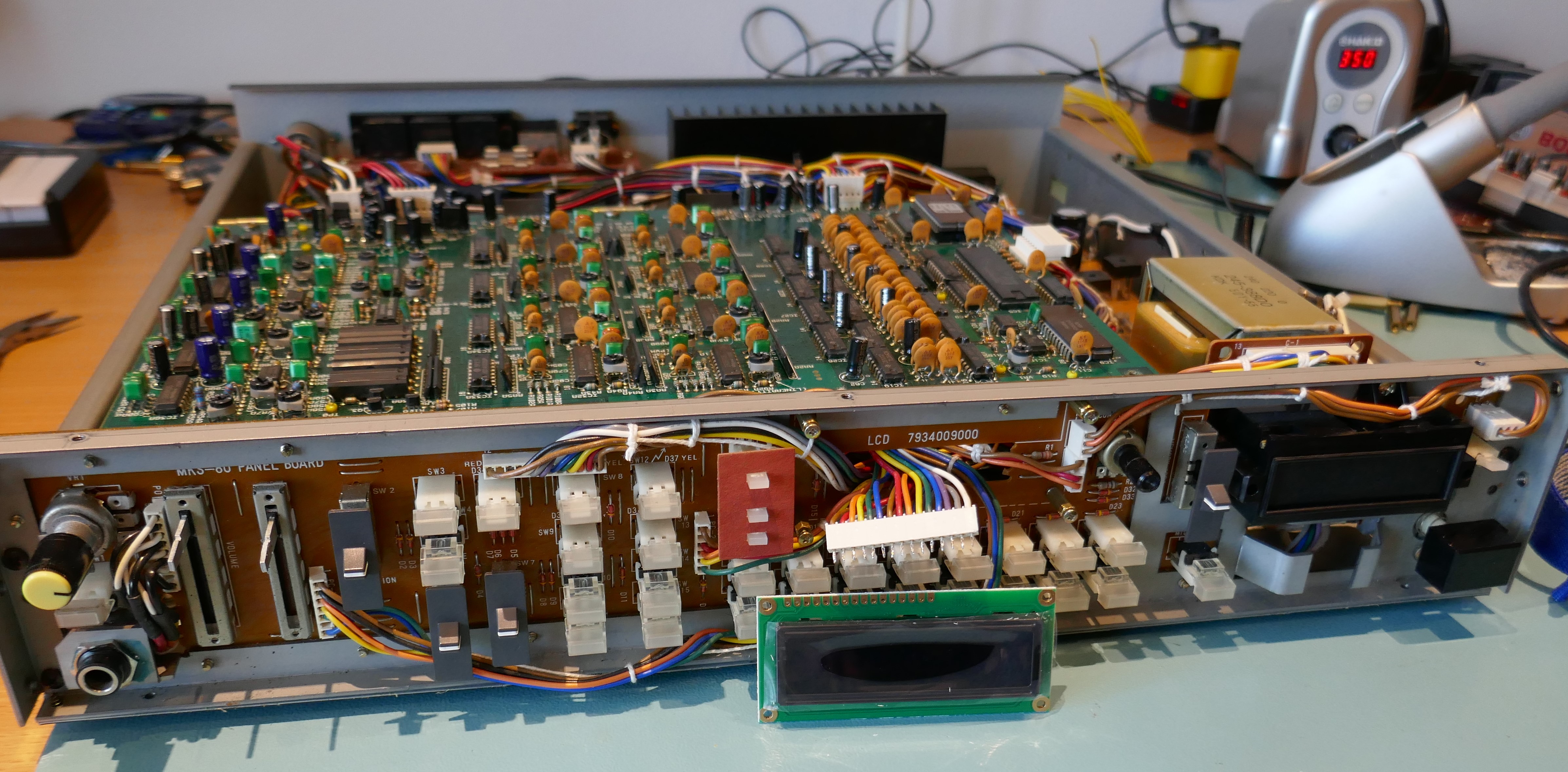
Winstar Display Connections
An OLED display has 16 pins to remain plug in compatible with old LCD displays. Only 13 are needed. The 2 side connections for the EL back light should be omitted.

The Winstar OLED pins 16, 15 and 3 are unconnected internally. The old display uses these to control contrast. As the pictures show, connecting up the first 15 pins and ignore the 16th, is perfectly ok for the Winstar OLEDs. The Winstar OLEDs also have built in decoupling capacitors on the power input and external ones are not needed.
Non Winstar Connections
If the type of OLED purchased has connections to pins 3 & 15, problems could occur. Issues have been reported where a different type of OLED initially work then fails later, although not proven that this was the cause. To ensure reliability, it is best practice to disconnect these wires in the harness.
Fitting & Soldering
Fit the display before soldering, the room available is very tight so it pushes the connector flush against the display PCB.
Before soldering, place a cloth or shield around the buttons and display to prevent damage to the buttons on the front panel.
Lead solder was used so that it can be easily removed if necessary. Lead free is ok to use but if it needs to be removed then a lot of heat is needed that can melt the wire to board connector.

Initial Testing
It is now time to plug in the MKS80 and test the new display. If it doesn’t light up, the connections are incorrect so turn off immediately and re-check everything. This can easily happen if the wires were cut and attached directly to the OLED display

Remove the film on the display.
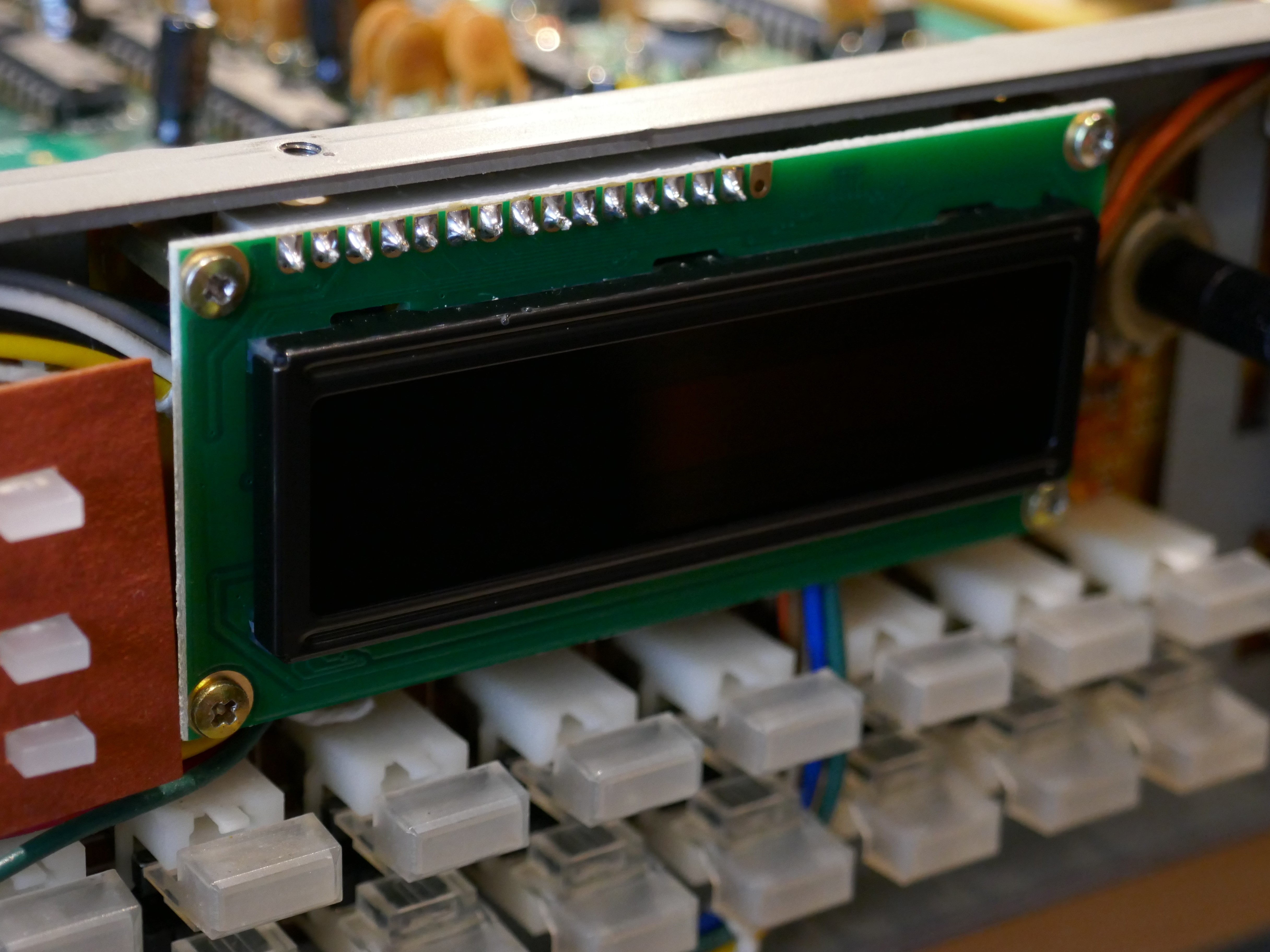
Here is a yellow one, the keen eyed will notice it isn’t soldered, this was to prove it out. It was carefully placed so that all contacts were under tension against the PCB. Not recommended to try unless you are confident a good connection is made.

Inverter Disconnection
This is not strictly necessary, however it does reduce the noise floor of the instrument slightly and if the yellow transformer is audibly noisy, then removes that too. On some instruments, they make a slight high pitch “whine”, this circuit is the culprit. The area on the assigner board is shown below.
It can be reached by removing the screws and stand offs holding the voice boards. Tilt the voice boards up slightly to gain access. When tilting the voice boards on their hinges, be careful not to raise too far and damage components on the PCB around the hinged area.

Simply remove the power filter, Inductor L2, located on the assigner board. It can be simply snipped out, however in this case I prefer to remove it by melting the joints from the top of the PCB and pulling out.
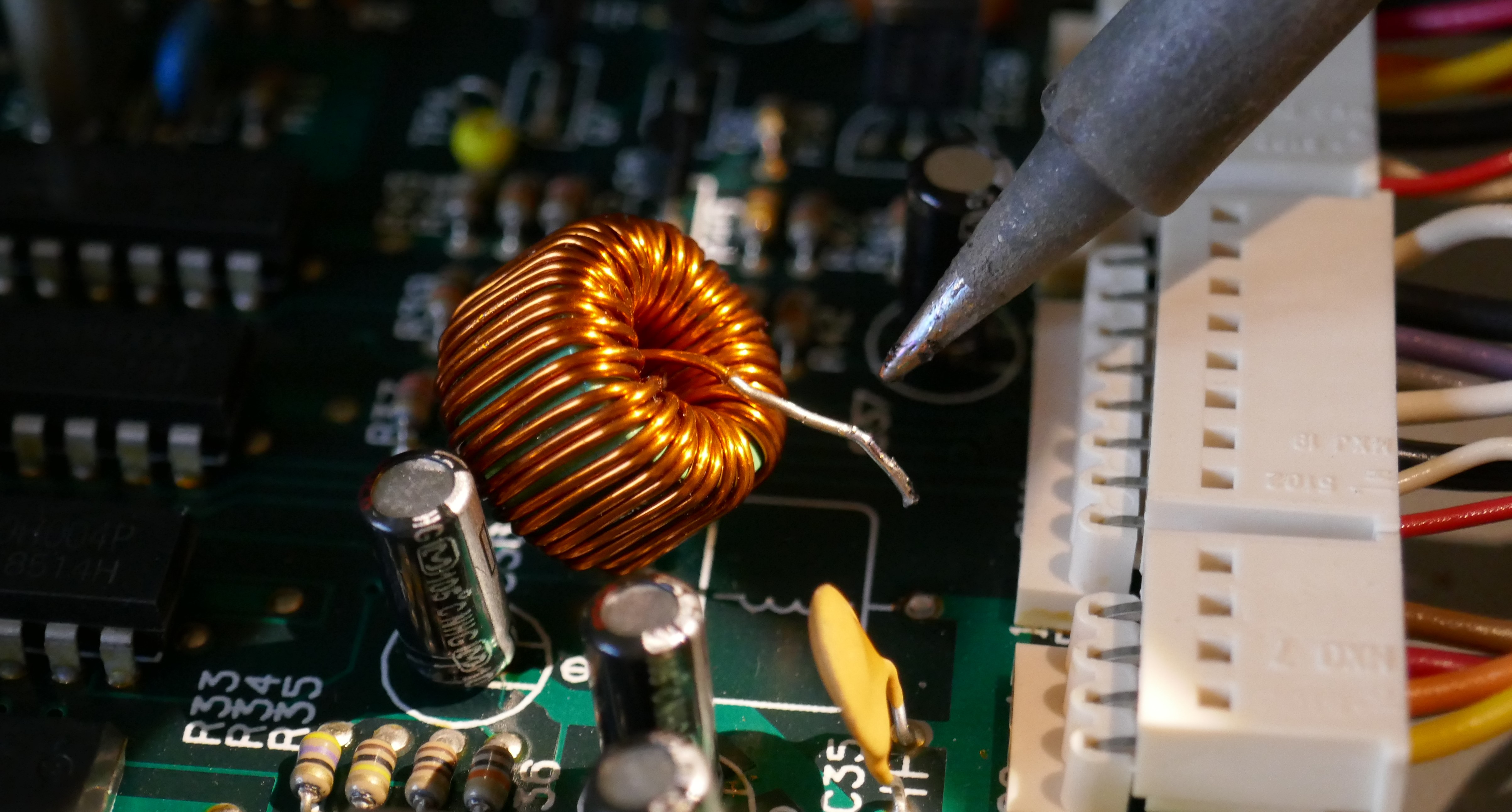
Picture below shows L2 missing. Note also the EL back light connector lower right hand corner that is no longer used.

Reassembly & Testing
Reassemble the voice boards taking care not to tighten the stand offs too tight. They are made of brass and easily break. They only have to be finger tight, otherwise they snap and you could lose a valuable ground connection as a result.
Attach the front panel, taking great care to to smash the MIDI status LED, it is vulnerable, so avoid force until the panel is seated properly around the cartridge port.
Retest the MKS80, it is a good idea to check that the buttons still work properly and it still makes music at this point before the lid is put back on just in case anything was disturbed.
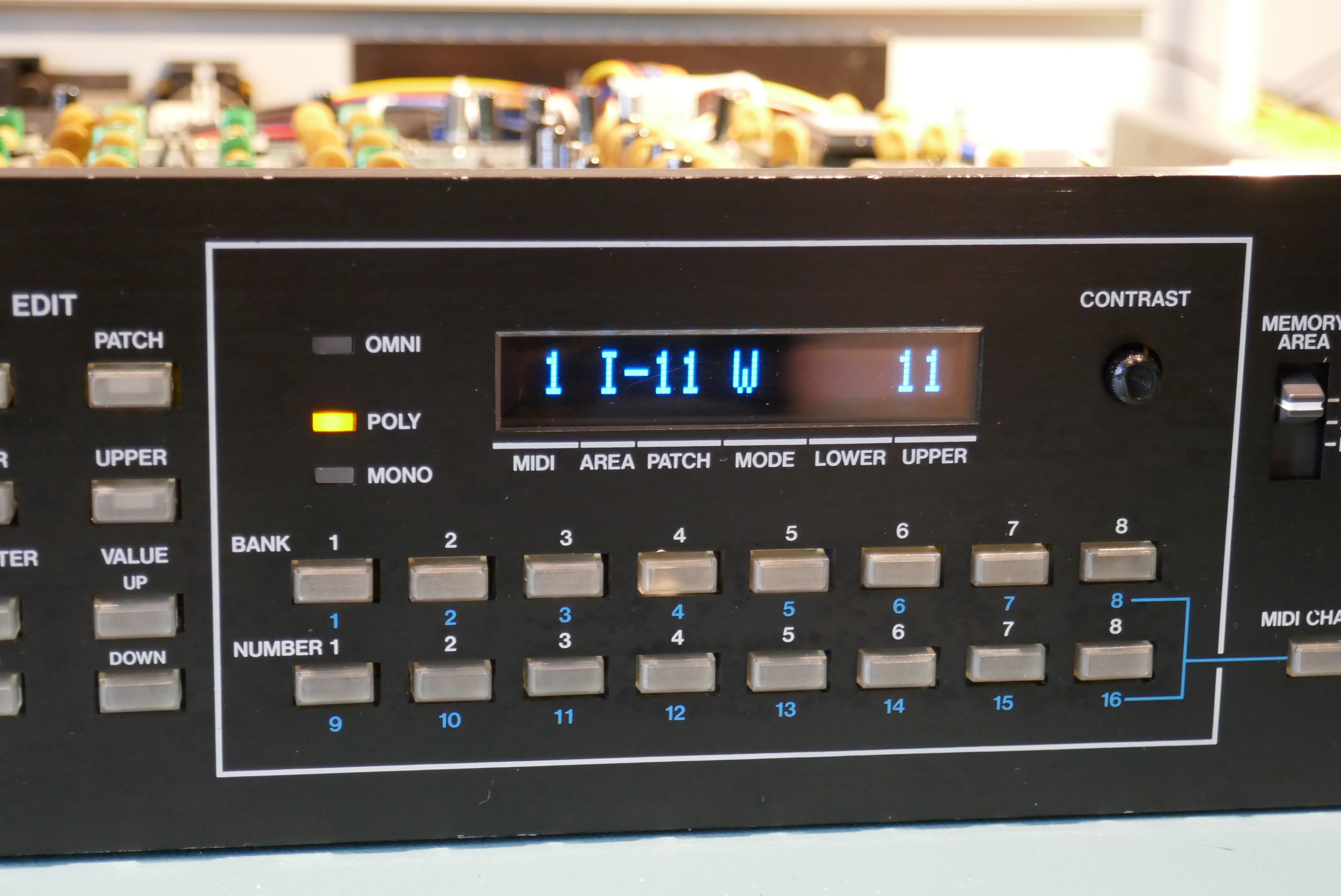
Now reattach the lid, rack ears and enjoy using it again but with a fabulous OLED display!
Copyright © 2020 Super Synth Projects & Peter Connelly Music, Guy Wilkinson & Peter Connelly
You must be logged in to post a comment.