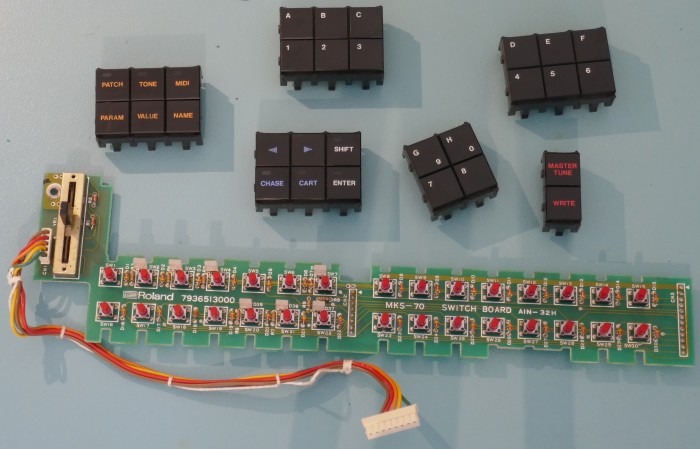
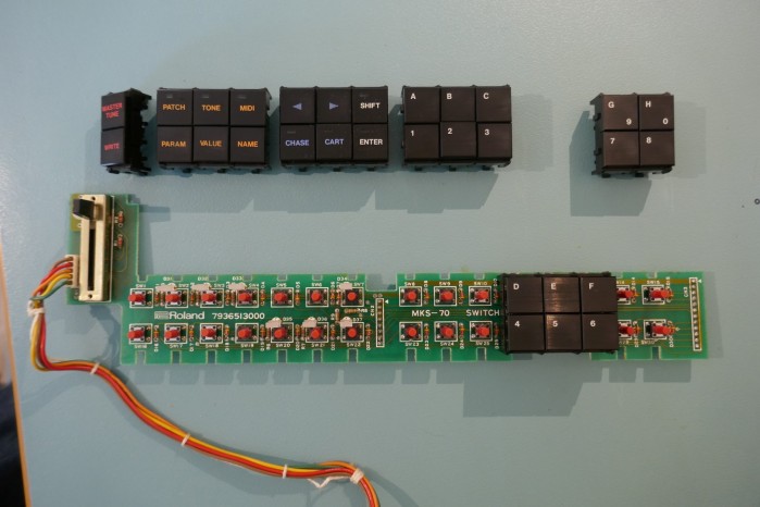
This is a step by step guide showing how to replace the switches on an MKS70 front panel as quickly and error free as possible in around 2 hours.
During this work it is a good idea to:
- Clean the plastic button carriers with mild detergent and water.
- Vacuum any dust out of the volume potentiometer.
Parts & Tools
30 x Alps SKHHBSA010 Tactile Switches (Mouser: 688-SKHHBS or Farnell: 2056814)
Desolder Pump, Fine Tweezers, Temperature Controlled Iron, Solder, Screwdrivers (that fit properly!)
Disassembly
After Removing the case lid and front panel, remove the screw at the top right hand corner of the Switch Board.


Using two hands, first at middle then at the right side, pull carefully at each pin header to free the switch Board from the display board. Take care not to use excessive force because otherwise damage could occur if the Switch Board is pulled out at an angle.

Let the Switch Board hang free before unplugging the connector to it from the assigner and carefully threading the wires and connector through the hole on the left hand side of the front panel.

When unplugging the connector, try to do this using the body of the connector and not just pull on the wires (unlike the picture below!).

The Switch Board is now free of the front panel.

Carefully remove the switch button banks from the PCB by pushing the plastic clips carefully from the rear of the PCB. To soften the clips, it is a good idea to warm gently with a hairdryer to avoid cracking the plastic.


Switch Removal
The technique shown below is the fastest and least damaging method. The purpose is to remove them without damaging the plated through holes of the PCB. There are other methods but not as quick nor less damaging due to the bent leg of each switch pin.
Turn over the PCB and use a desolder pump to remove the solder from each switch pin.


Once complete, do a visual check of the top of the switches to look for holes that still have too much solder in them. Examples are shown highlighted with arrows in the picture below.

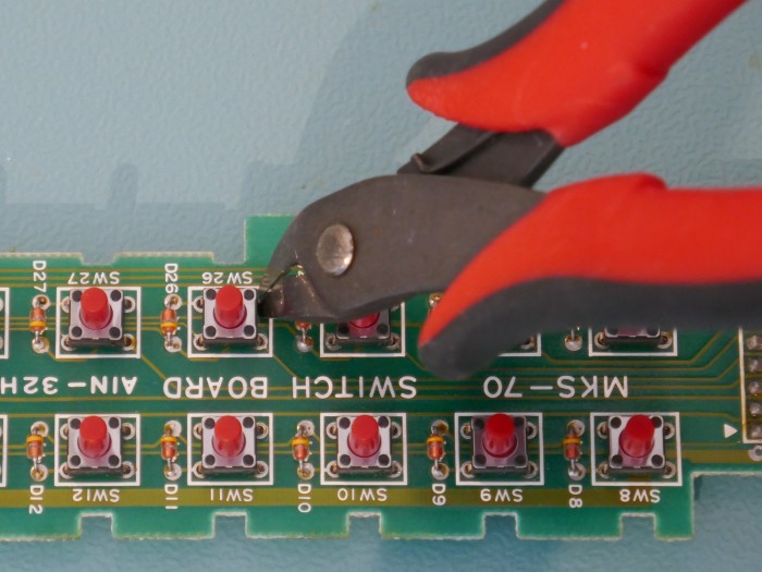
Turn over the PCB and using sharp edge cutters snip 3 of the 4 legs of each switch. In most cases the pins will just fall out.
For the switches that don’t simply fall out, heat the 4th leg and remove the switch.

Switch legs that are still in place, remove them with a little heat and tweezers.

Once all the legs and switches have been removed, use the desolder pump as required to make any partially blocked holes free. Sometimes, solder that is difficult to remove is simply taken away by refilling the hole with solder and removing with the pump again.

Fitting New Switches
Once the holes are all clear of surplus solder, fit the new switches making sure that they are completely perpendicular to the PCB. If not completely flush to the PCB, the button banks won’t fit properly and it will contribute to “sticky button syndrome”.
Test each switch for positive action: Not all switches are made exactly the same, some have a more positive action and “click”. The bottom row of buttons need to have switches with the most positive “click” and most actuation force to prevent “sticky button syndrome”.

Turn the PCB over and solder all the switches in place.

Perform a visual check of the top side of the PCB to make sure that solder is on the top of the pad. This ensures that a connection is made on both sides of the PCB and that a through hole connection is properly made. If not, simply top up the joint from the top without burning the switch body.
The picture below shows a good joint on left pointed to by a green arrow and a bad joint on right pointed to by a red arrow.

Reassembly
Reassemble the button banks onto the Switch Board. It is a little tricky because you have to push the button carrier rather than the buttons themselves.

After fitting the buttons ensure that all buttons “click” and feel smooth, any jamming or refusal to click usually means that the switch underneath is not level or flush to the PCB or too much dirt is inside the plastic switch housing and mechanism.
Sticky Button Syndrome
Buttons when pressed can stick down when pressed at a corner. It is most likely to affect the bottom row.
As the picture shows below, the reason is that the originally smooth sliding surfaces of the plastic housing become dirty or wear. This can be remedied to some extent with careful switch choice: Testing each one and fit most positive action ones on bottom row.
It may be possible to remove the button from the housing for cleaning, but the risk of damaging the plastic clips is too great, after 30 years they are fragile and best left alone.

If this doesn’t work, then there are two options, first one is to apply silicone grease to the surfaces on the bottom right hand corner as shown in the picture shown below. It is vital that grease is not spilled on the front of the button! Silicone grease is safe for use on plastics and must be applied sparingly.

A more drastic approach is to apply grease on inner surfaces as shown in the picture below too. This is time consuming and adds very little improvement but can help in combination with the other adjustments. It also puts more grease on the assembly that is not desirable.

If any grease ends up on the buttons, it can be removed with IPA on a cotton bud but avoid getting IPA on the legend as it will be dissolved.
Completion

Reassemble back into the MKS70 front panel in reverse order, taking care to not use excessive force on the PCB stacking headers (Switch to Display Board connectors).
Copyright © 2020 Super Synth Projects, Guy Wilkinson
You must be logged in to post a comment.