This guide shows how to replace a worn Alps encoder with a new Bourns PCB mount equivalent that costs around 1.5 GBP or 2 USD. This guide shows the JX10 getting the treatment, however the same encoder and principles apply to the MKS70 and other vintage Roland Synths.

The encoder suggested also works very well in the Roland Alpha Juno-2 but the wire colours are different. Keith Meiere of Llamamusic has created a guide that uses the instructions below but gives the correct wire colours for the encoder pins. See this page here for details: Alpha Juno-2 Encoder Replacement
Keith has also identified that the same encoder also works in the Juno‑1, HS‑10 and S‑10 variants also.
Encoder Requirements
Finding a suitable encoder and trialing different types was an exhaustive exercise. There are many types available and finding something that fits and gives out the correct timing is challenging. See later section about “detented” types and what to expect if using them.
Many also come with built in push switches, these also work but the switch contacts can be left unconnected (or “hot wired” to your favourite “button” on the panel board).
- Detentless
- 2 Channel
- 15mm Shaft Length
- 6.00mm Flatted Shaft
- 24 to 40 Pulses
- 3 Wire mechanical “switched”
- Non-Switch
The type selected and used in this guide is a Bourns PEC11R-4015F-N0024. It is readily available from distributors:
UK / Europe: RS Components, part number 7816824
USA / Europe / UK: Mouser
Replacing The Encoder
Assembly Removal
First locate the back of the encoder and examine the four clips around the encoder assembly, removing this is tricky without damaging the retaining lugs in the plastic moulding.

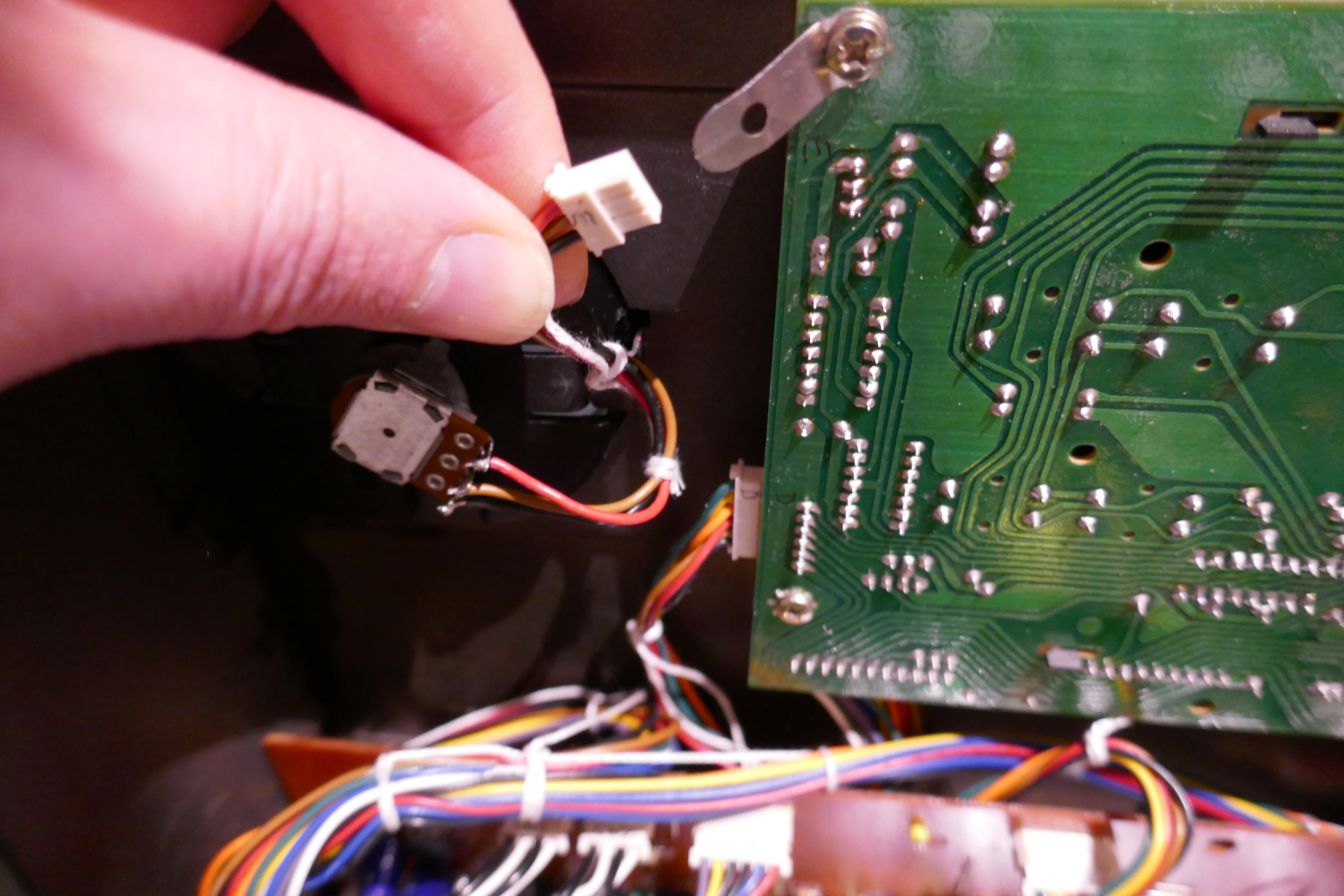
First, remove the 3 pin encoder connector.
Old ABS plastic can be very brittle so before attempting to remove the assembly, use a hairdryer to gently warm the plastic. Take great care not to overheat because the plastic can deform easily.
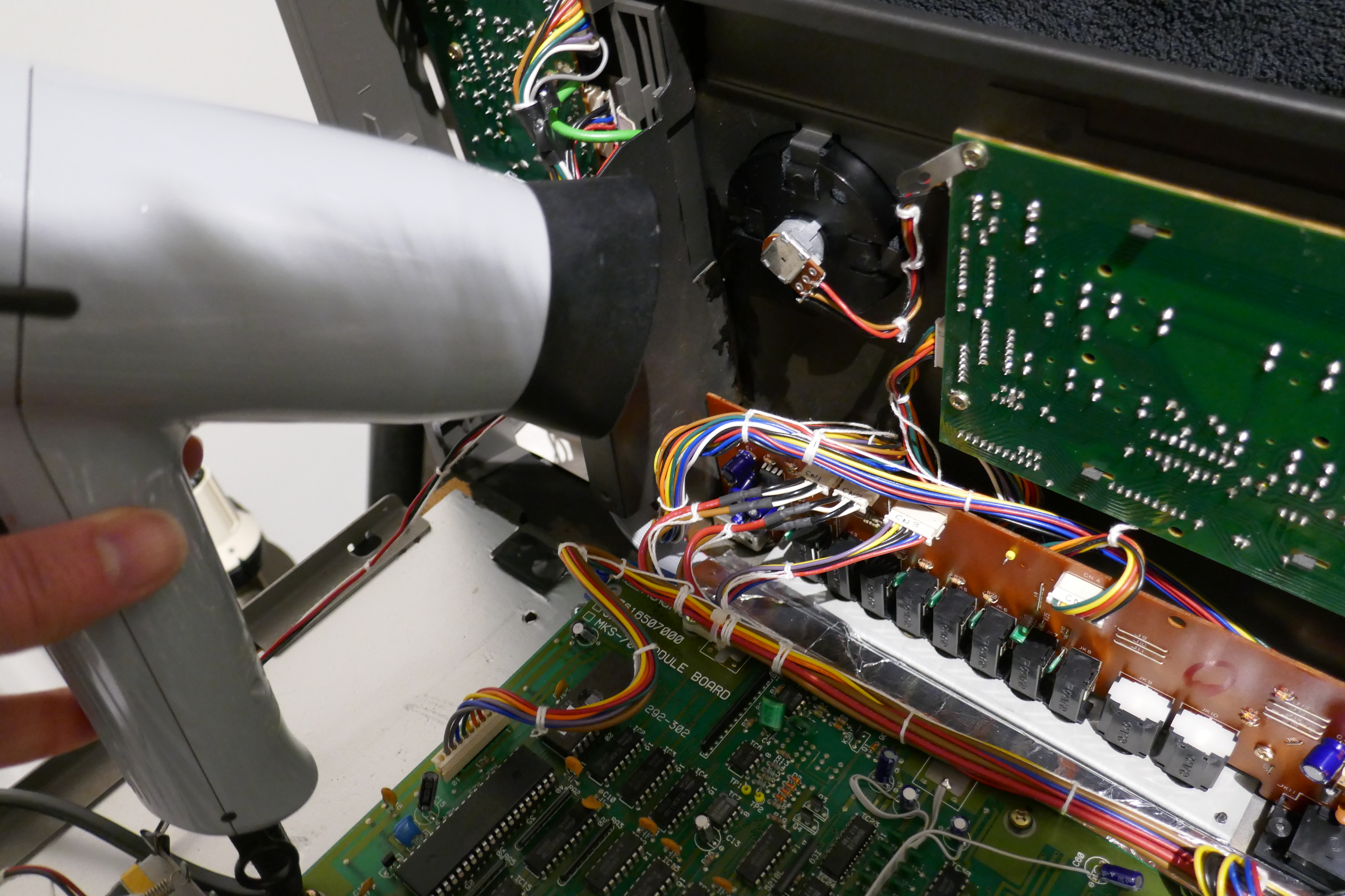
Once warm, the retainer clips should be much less likely to break when they are carefully squeezed whilst the encoder moulding is pushed out from the back of the panel.
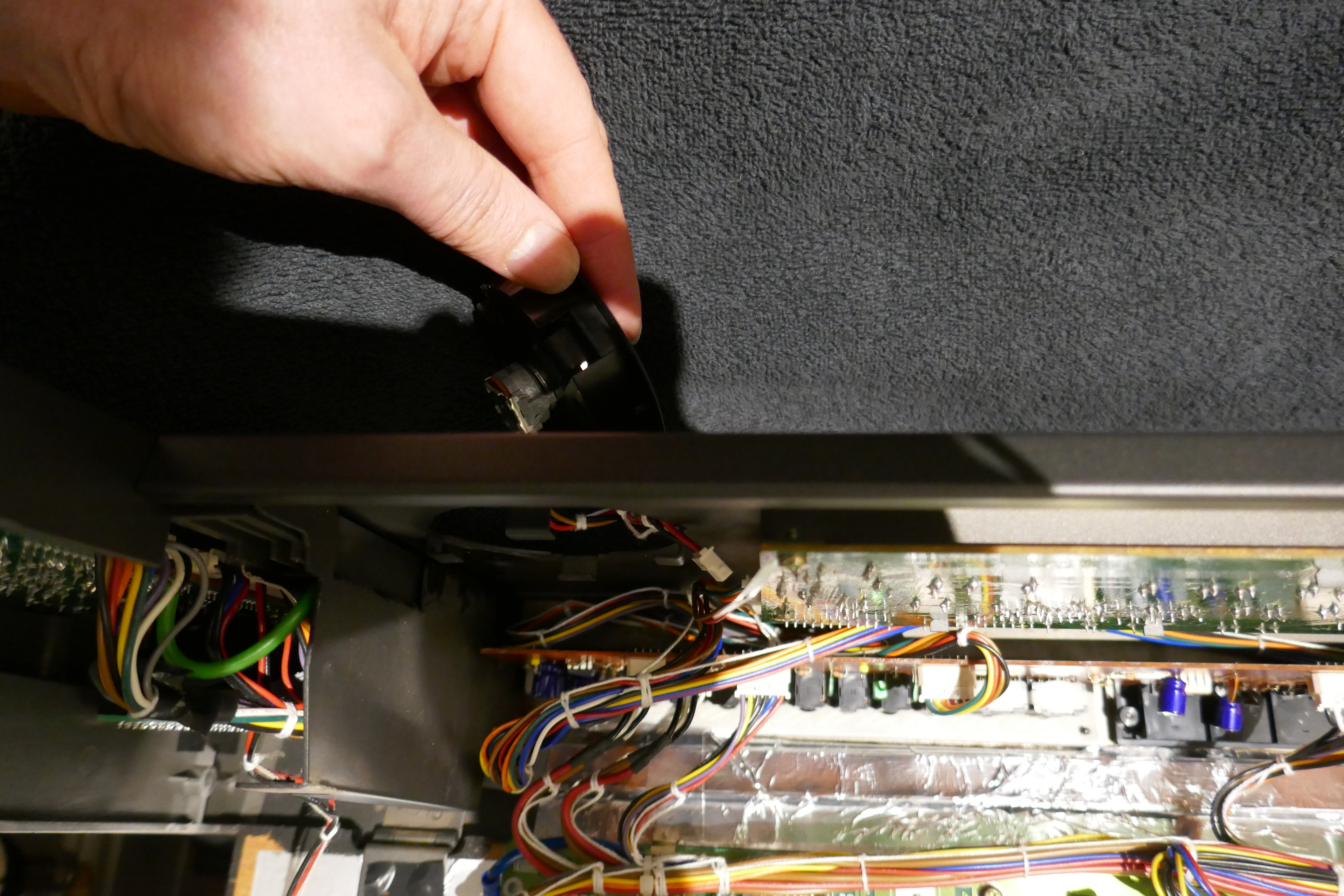
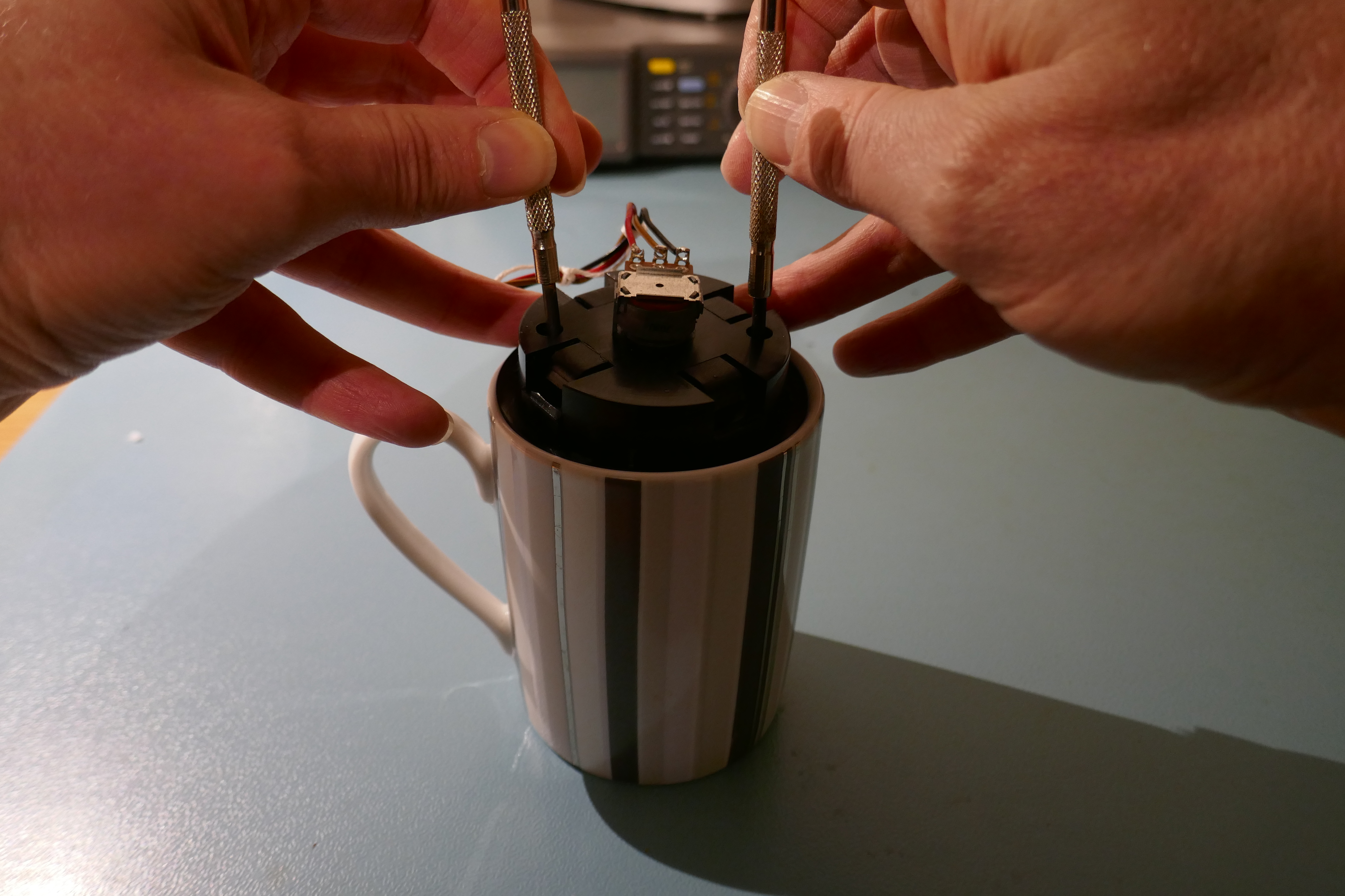
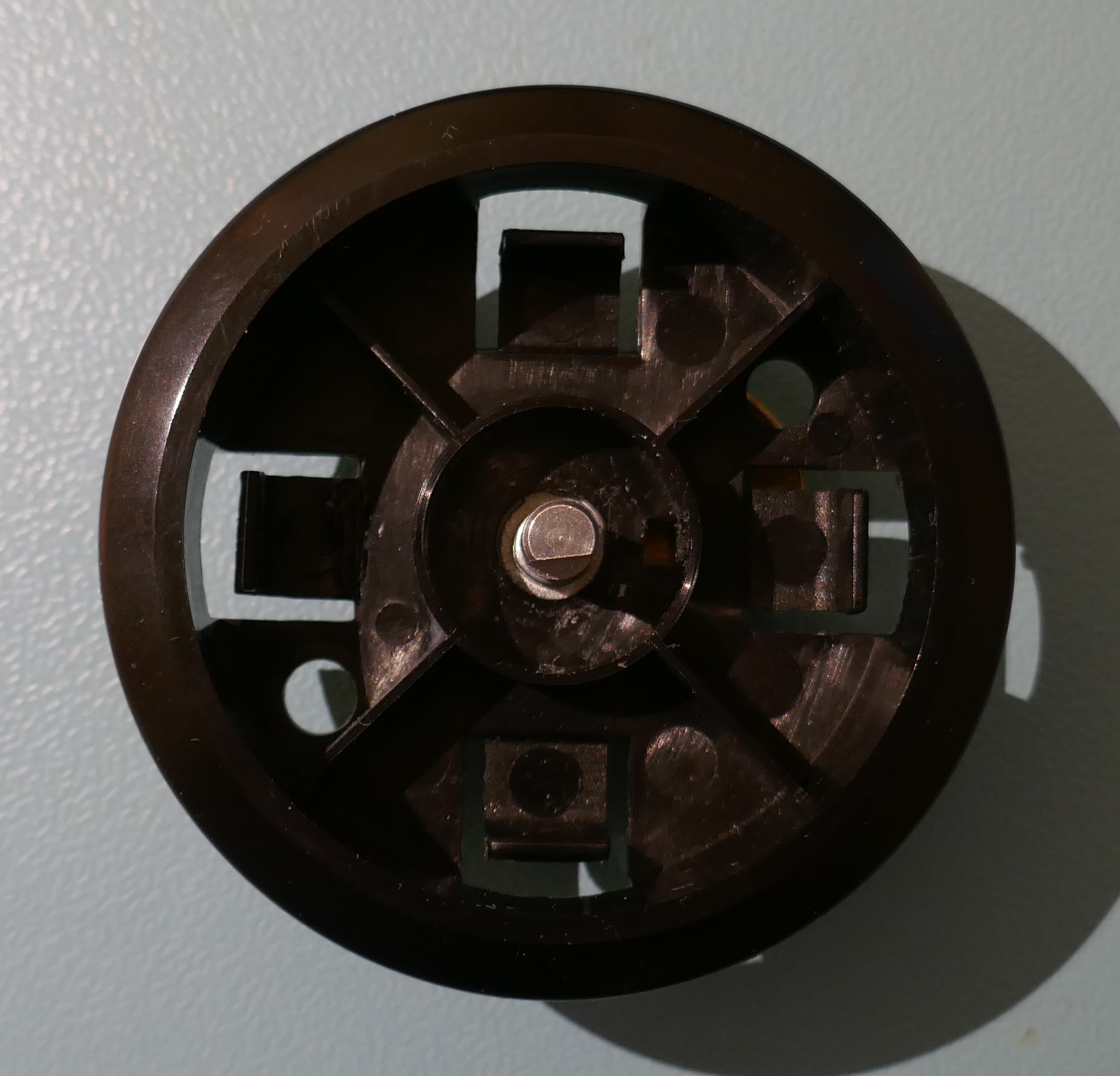
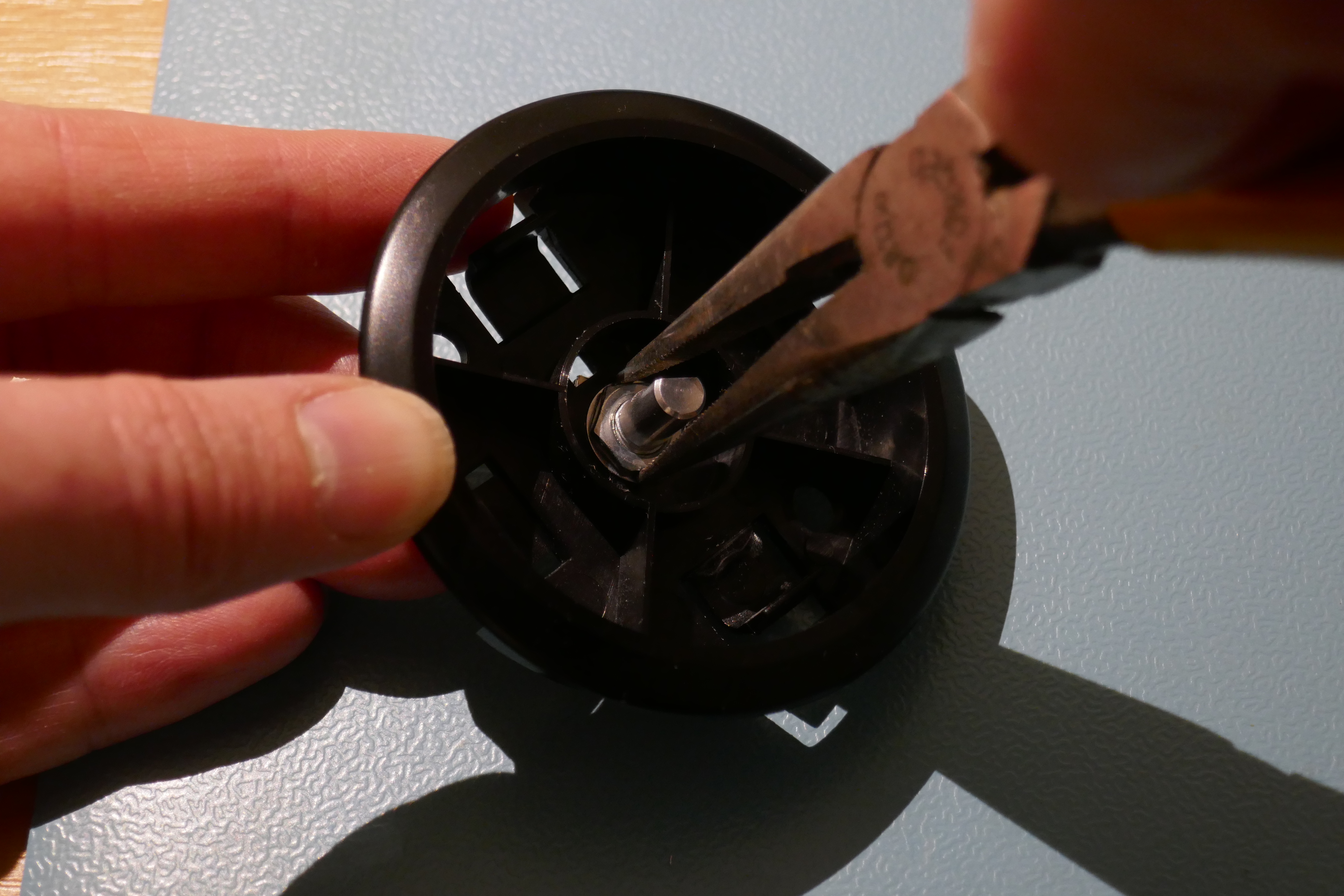
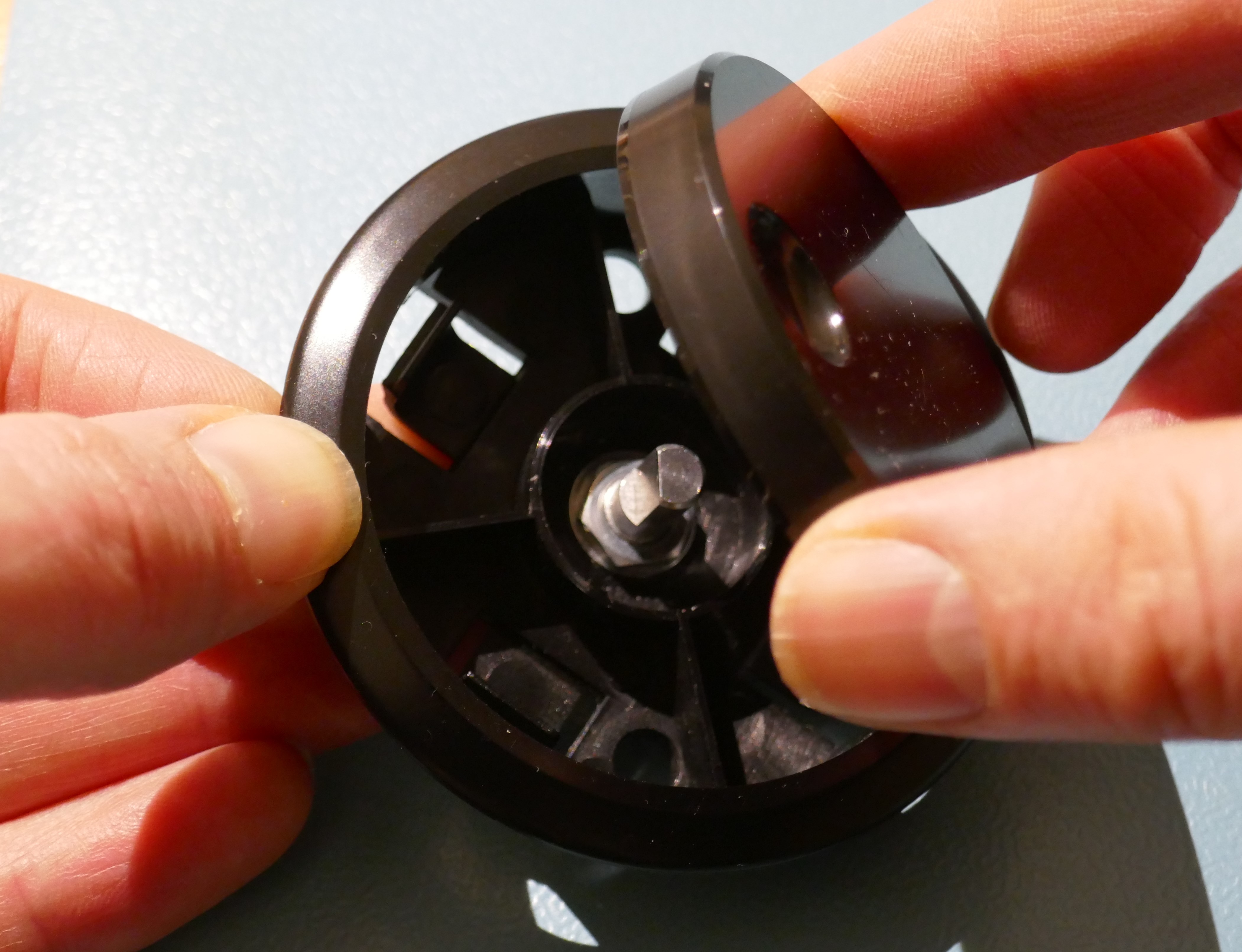
Removing The Wheel
Removing the encoder wheel is straightforward, you need a suitable sized cup and two screwdrivers to “poke” the wheel out from the rear.
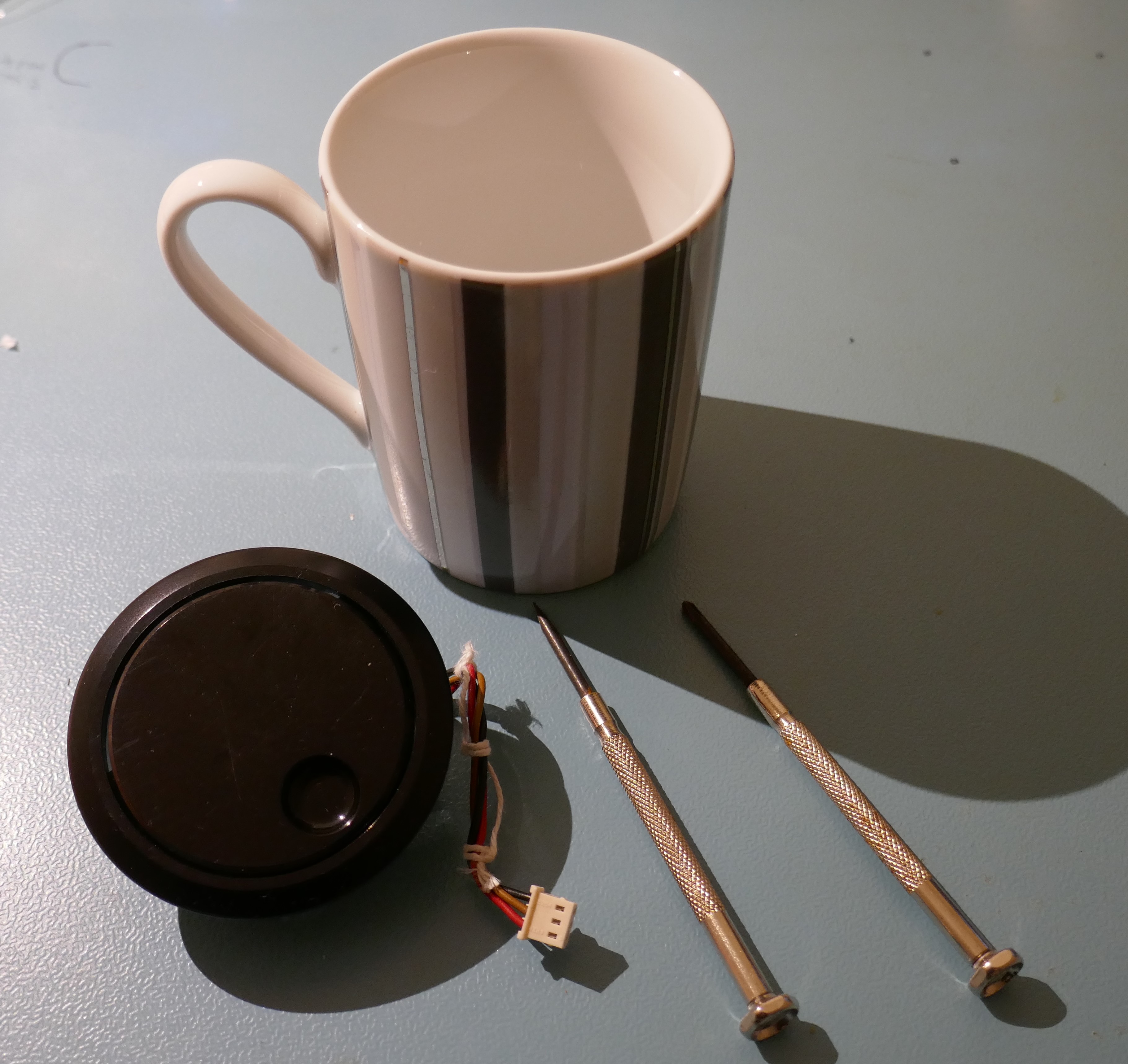
Press with gentle and even pressure through two location holes in the moulding. The wheel will just slide off easily and pop off with very little pressure. Light and even pressure on the two sides is essential otherwise the wheel mounting hole could be damaged.
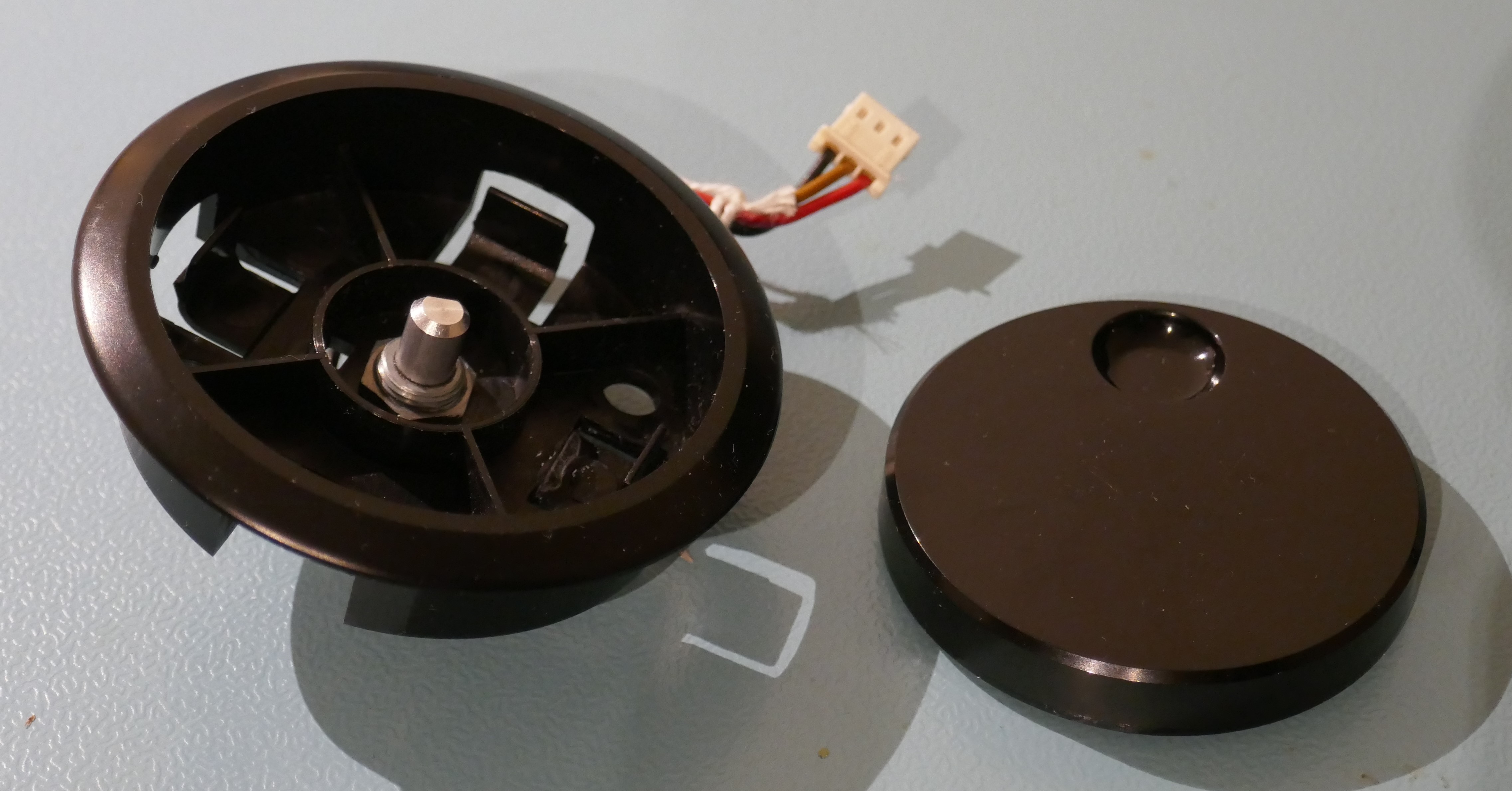
The wheel is off and the fixing nut can be seen.
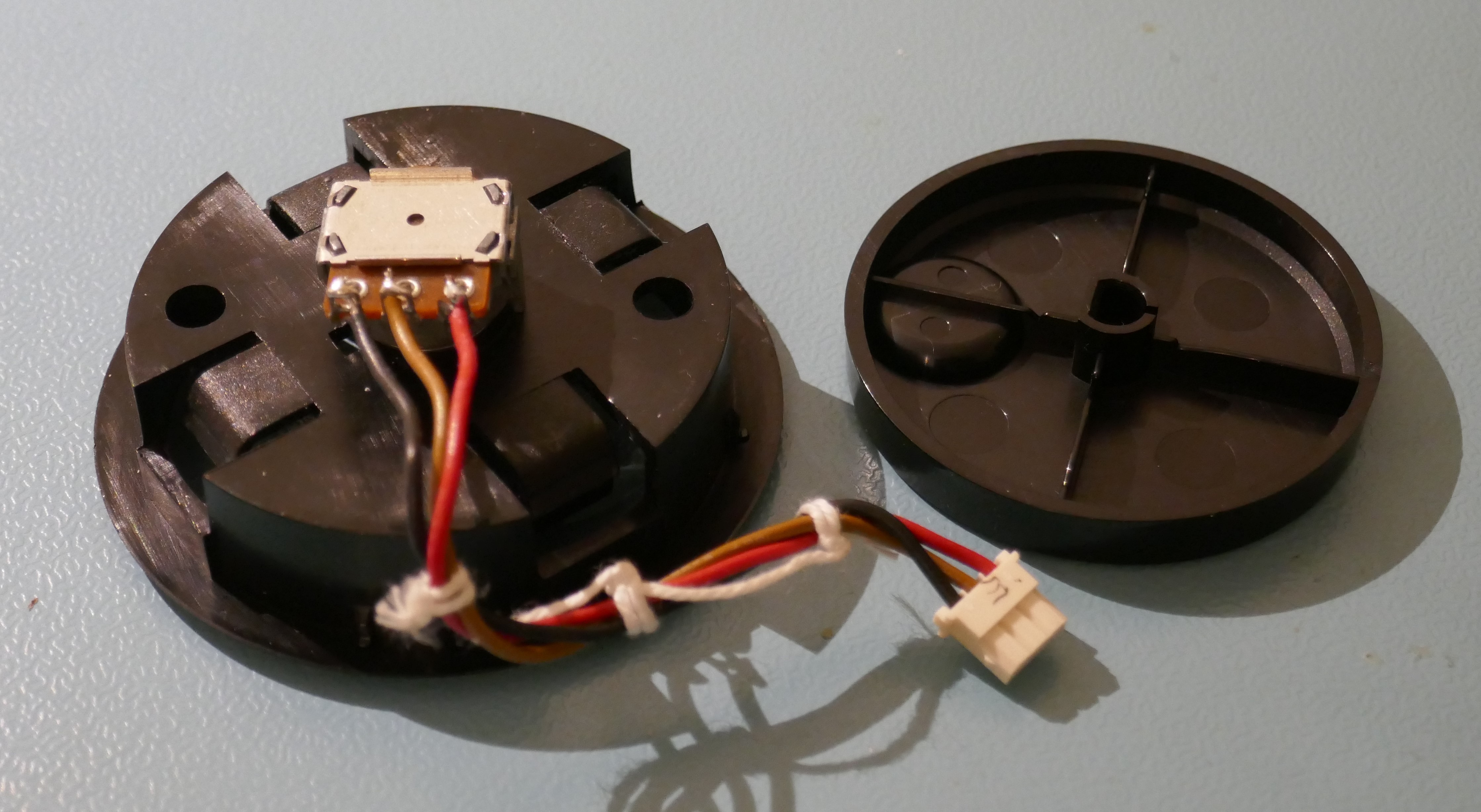
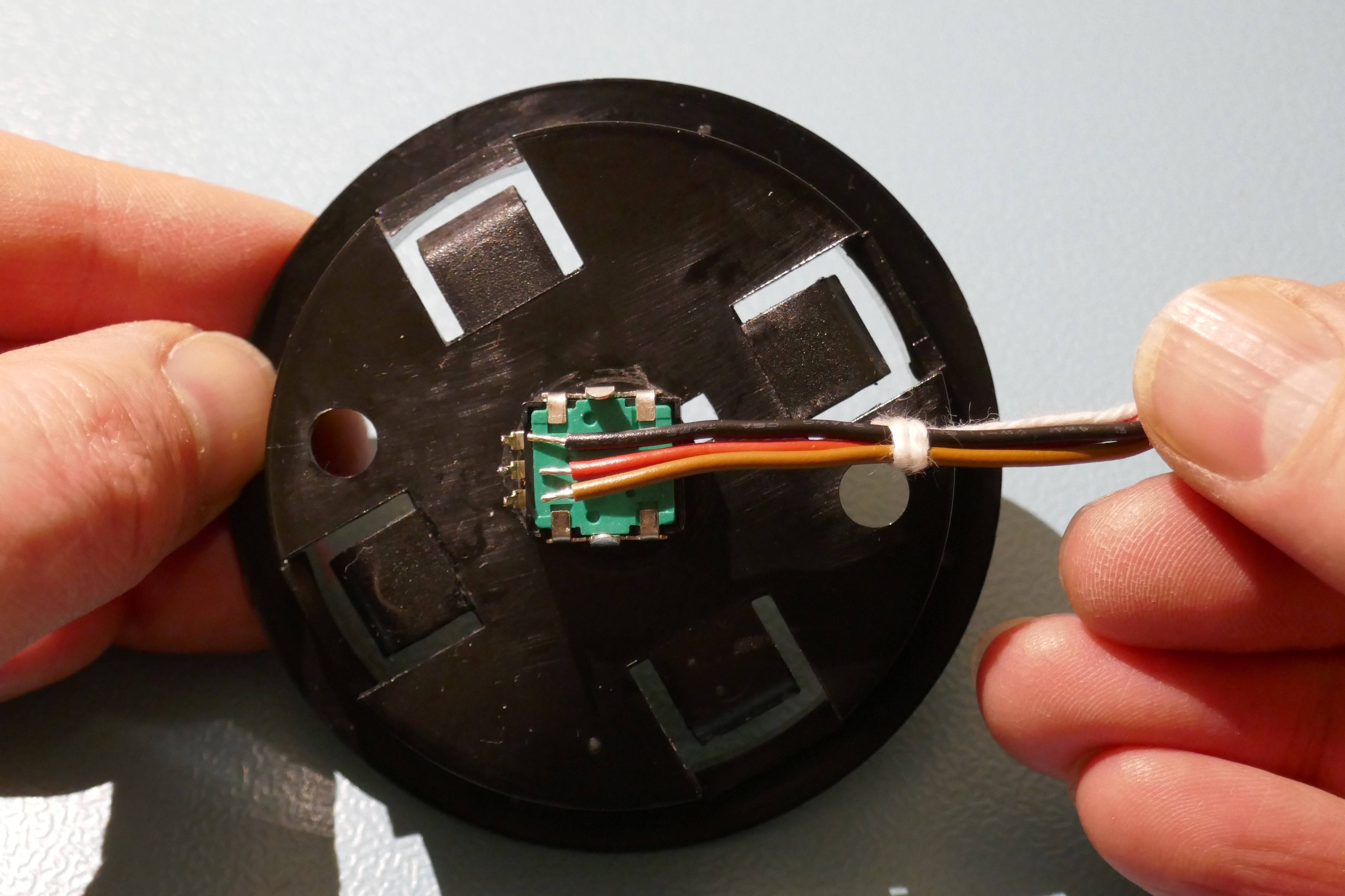
The rear of the encoder assembly reveals the 3 wires: Red – Common 5 volts, Black – Signal B, Brown Signal A.
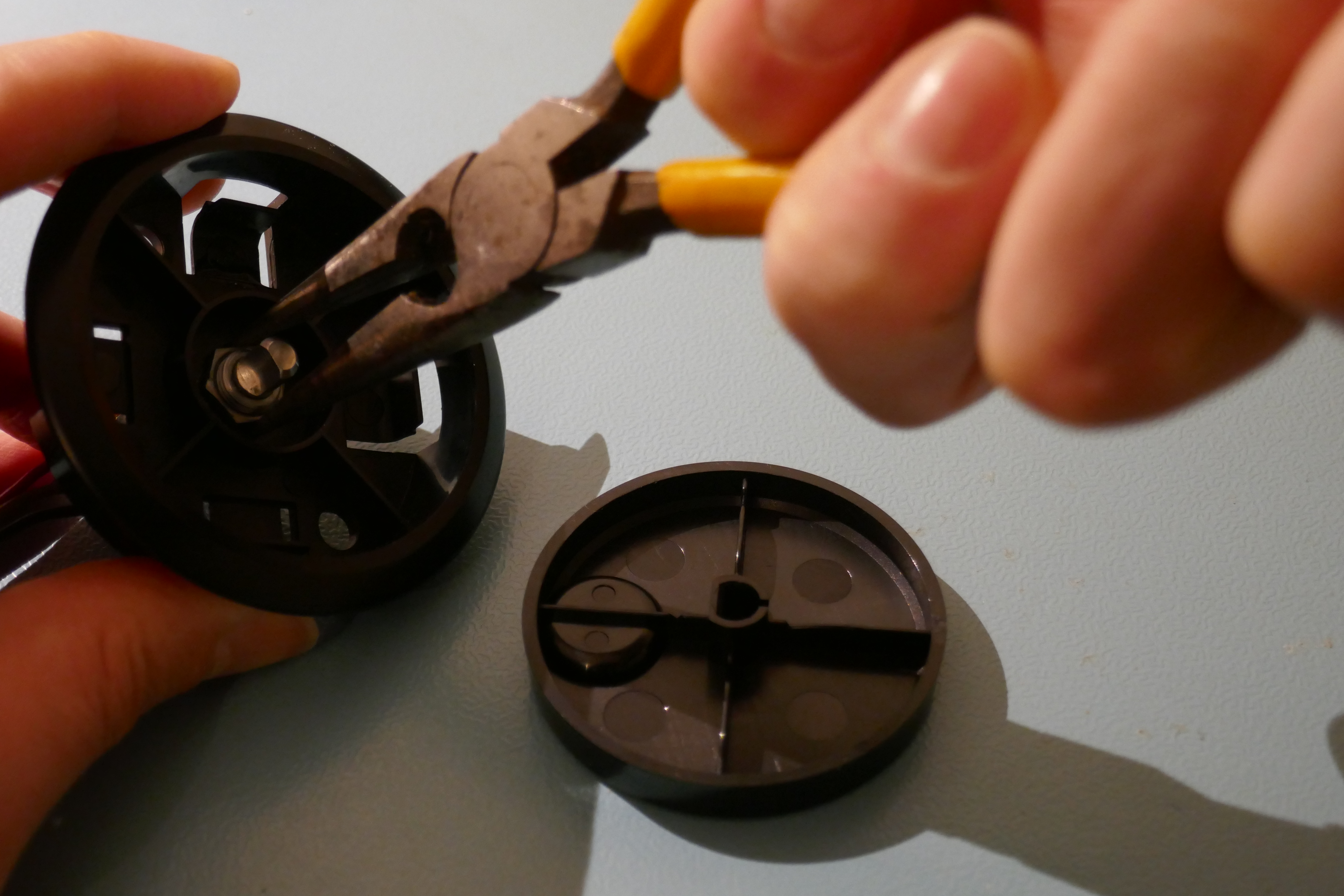
Removing Old Encoder
Loosen the nut carefully with long pliers and remove it by hand.
Fitting New Encoder
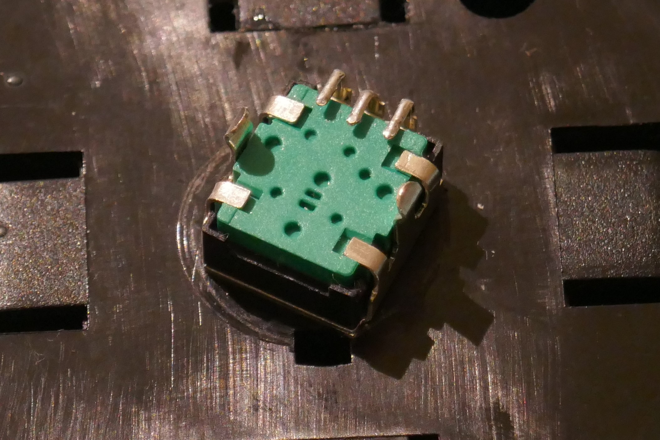
The new encoder, Bourns PEC11R-4015F-N0024, is not the same as the original:
- Bushing is smaller – Careful alignment is necessary to keep wheel central
- PCB Mounting type – Wire to pin attachment requires insulation & securing
- Pin order is different

The bushing is a “baggy” fit and there isn’t a locking tab.
Clean the excess grease off the base of the encoder to ensure a good friction fit when secured in place.
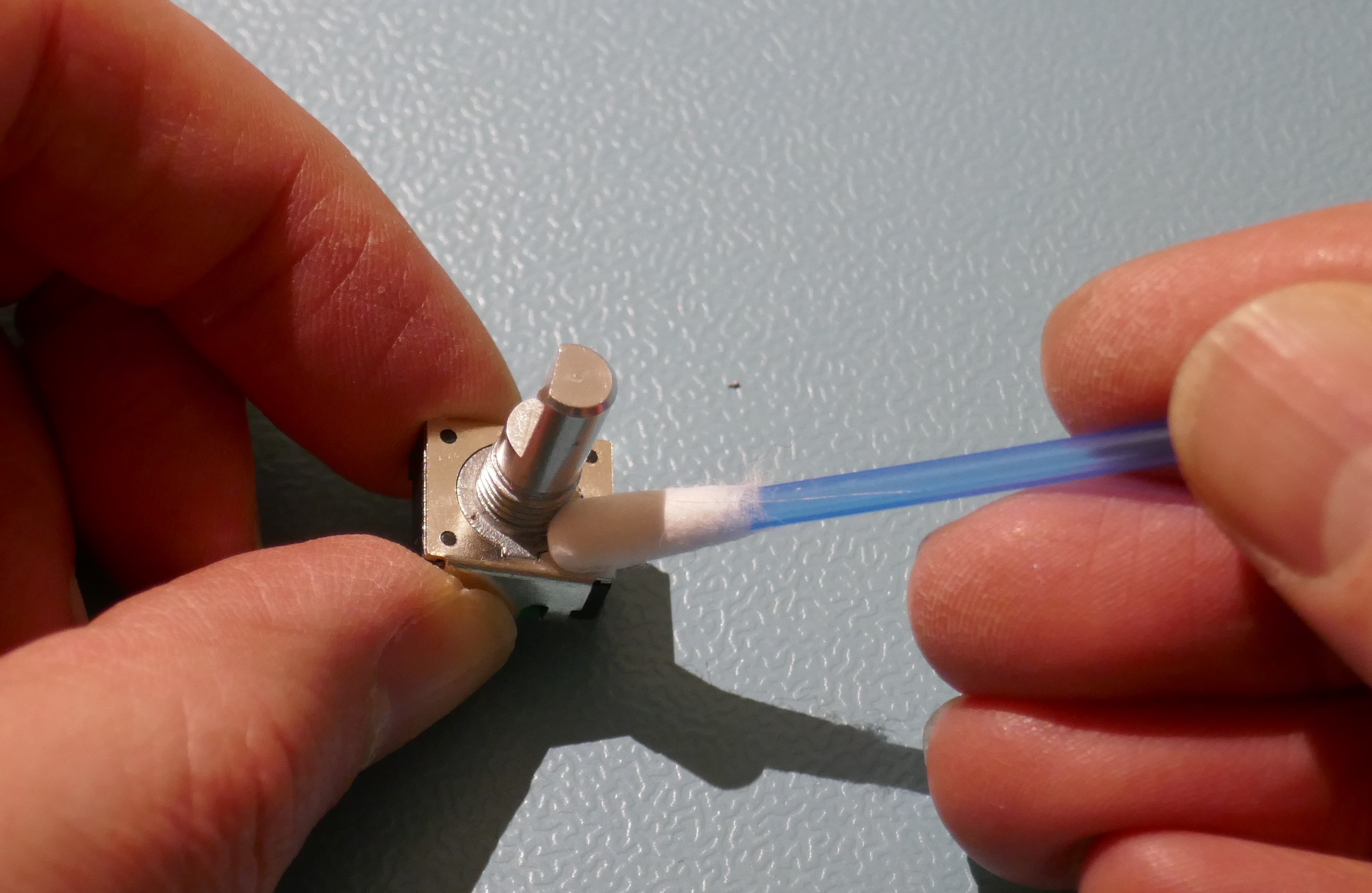
Carefully tighten whilst aligning centrally.
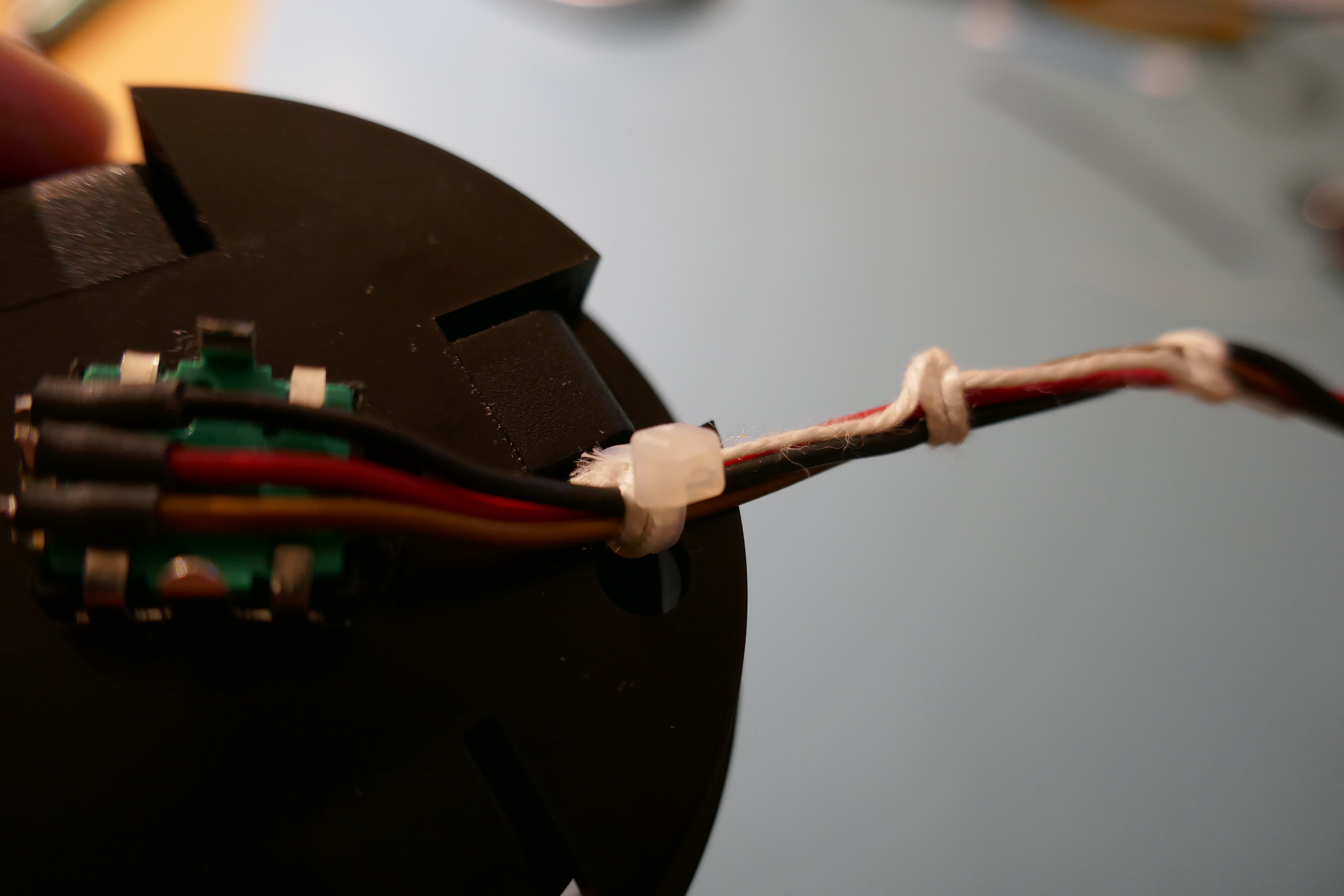
Set the position of the encoder body so that when the wires are in position, a cable tie can be placed to secure the wires using one of the holes. This will also prevent the encoder from falling off and shorting a PCB underneath should the nut ever come off.
Fit the wheel and if alignment isn’t perfect then manipulate the encoder body (by rotating it slightly) on the rear to get it into position, it should still be able to rotate slightly with force (however take care not to use too much force).
To attach the wires, the pins have to be carefully bent at a right angle. They could easily break so do this slowly.
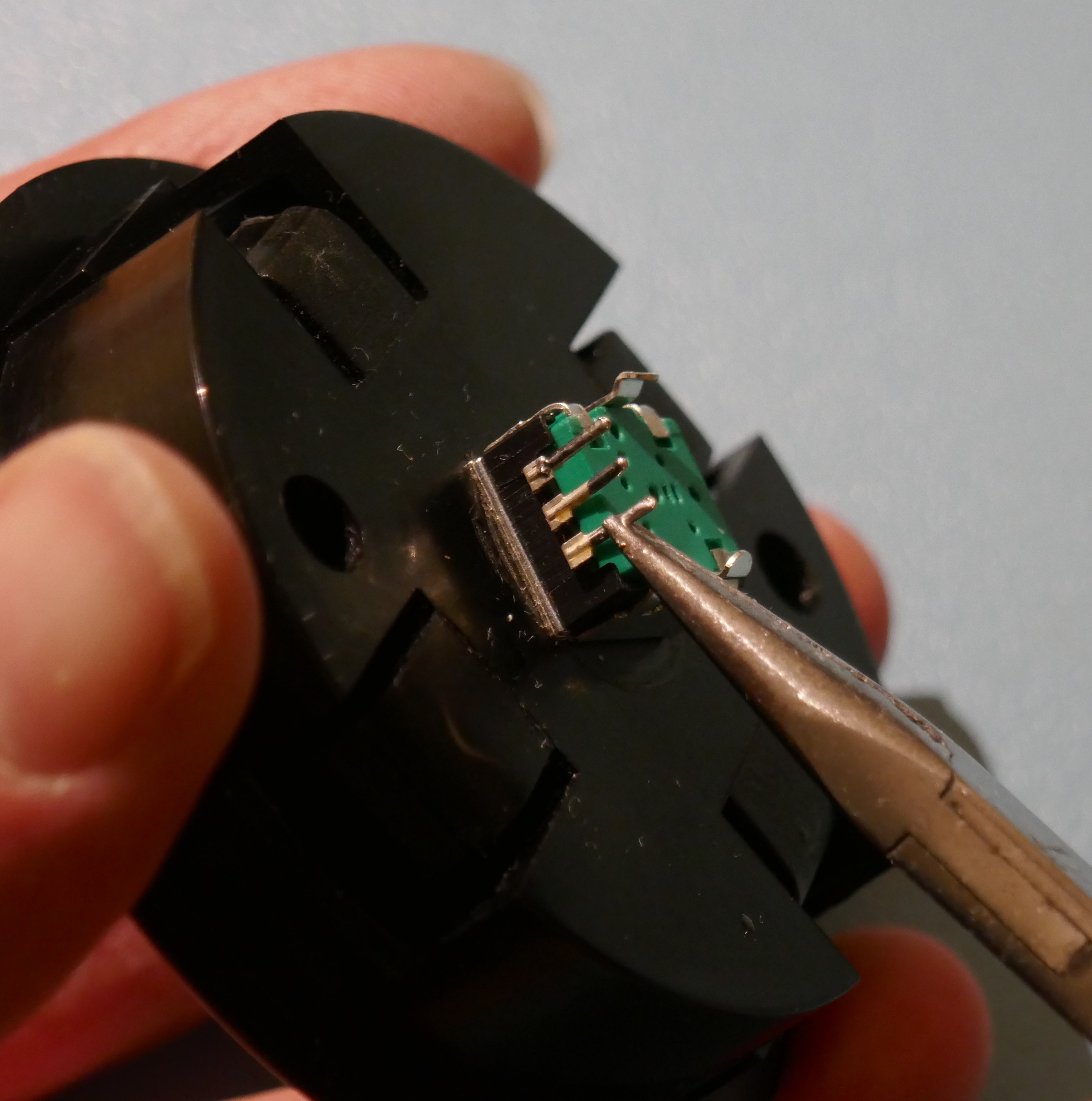
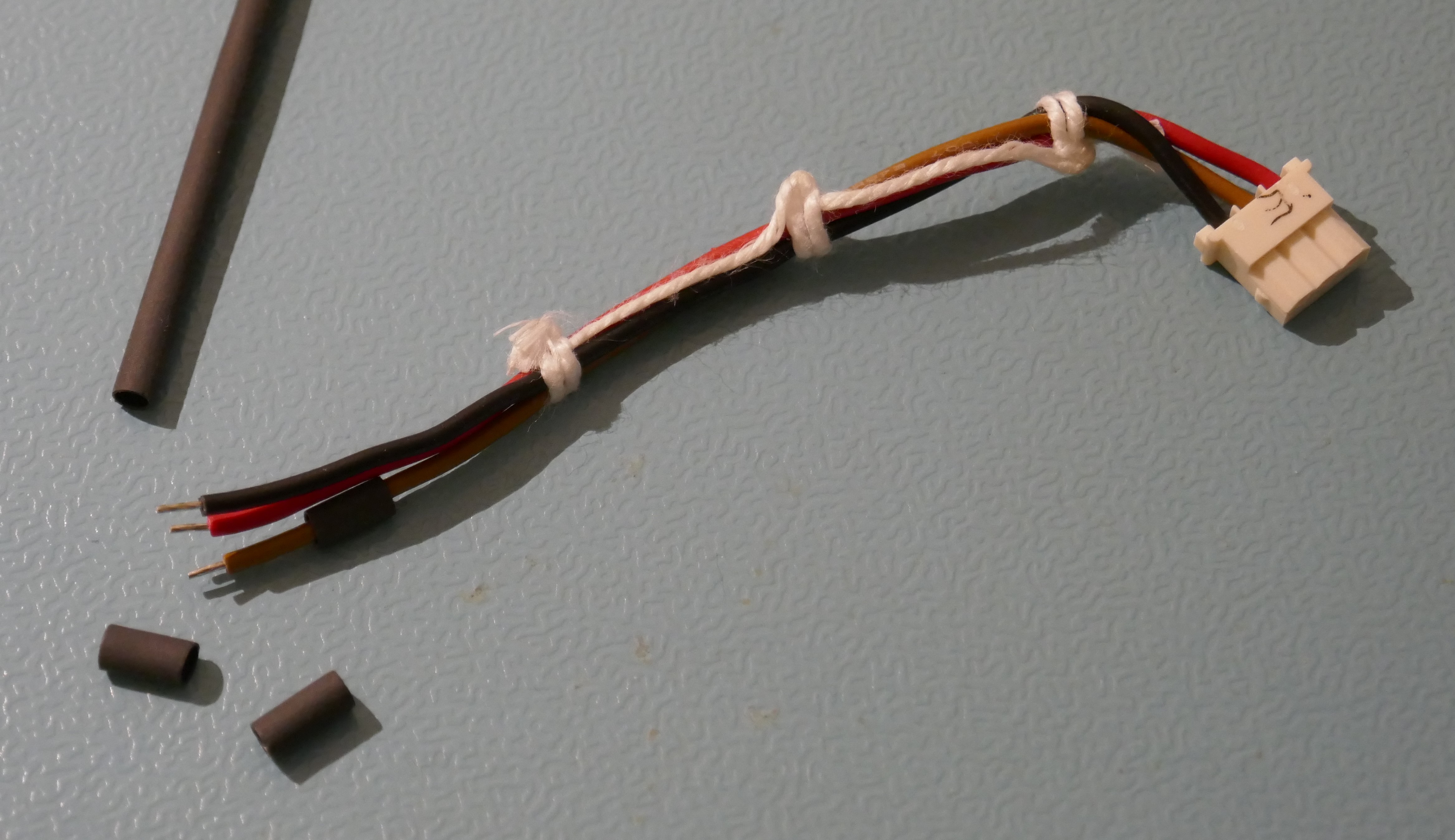
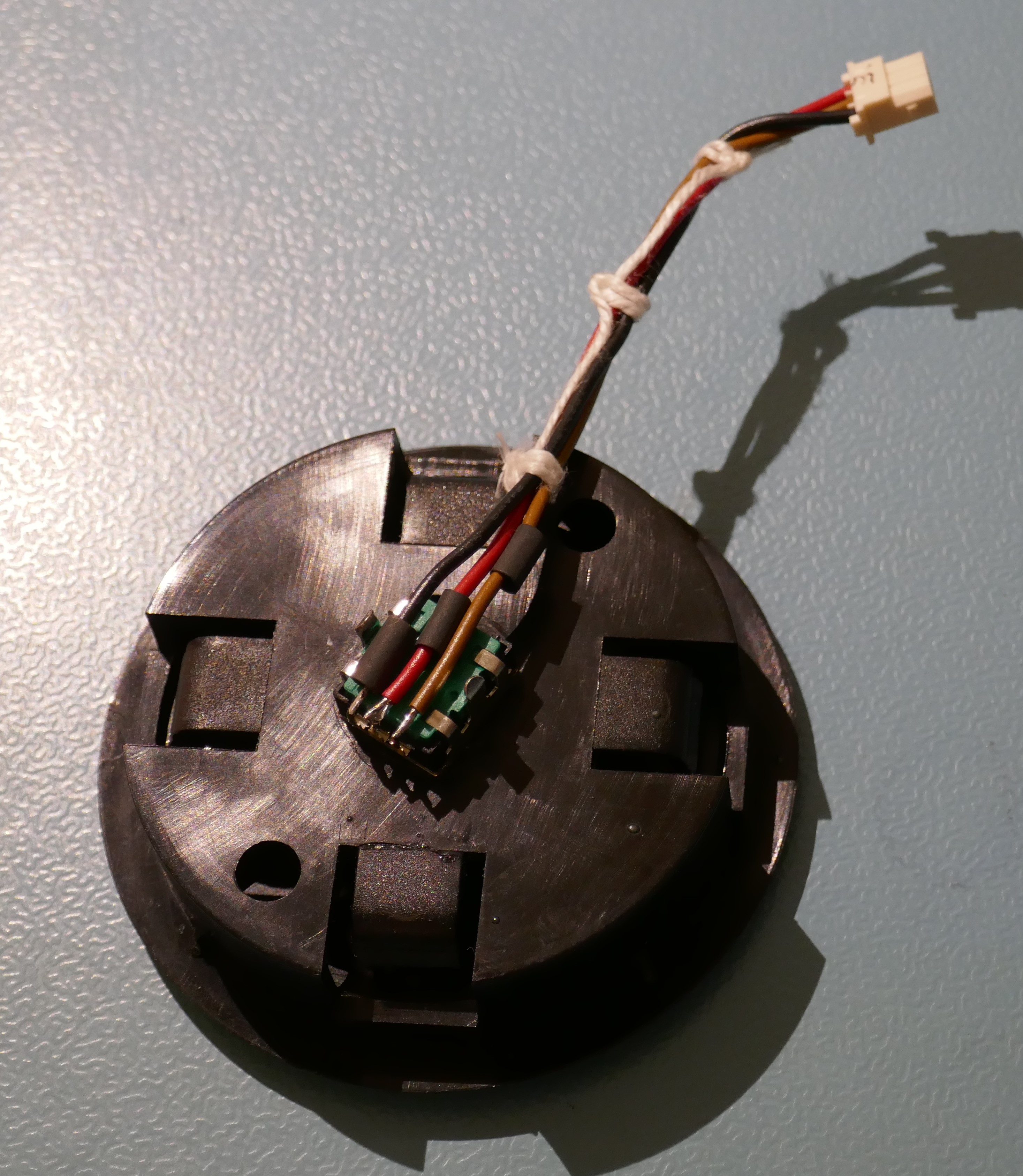
Trim the wires and manipulate them so that they are in order Black, Red and Brown. Tin the wires with solder and place some short pieces of 3mm heatshrink tube on them.
Tin the pins on the encoder.
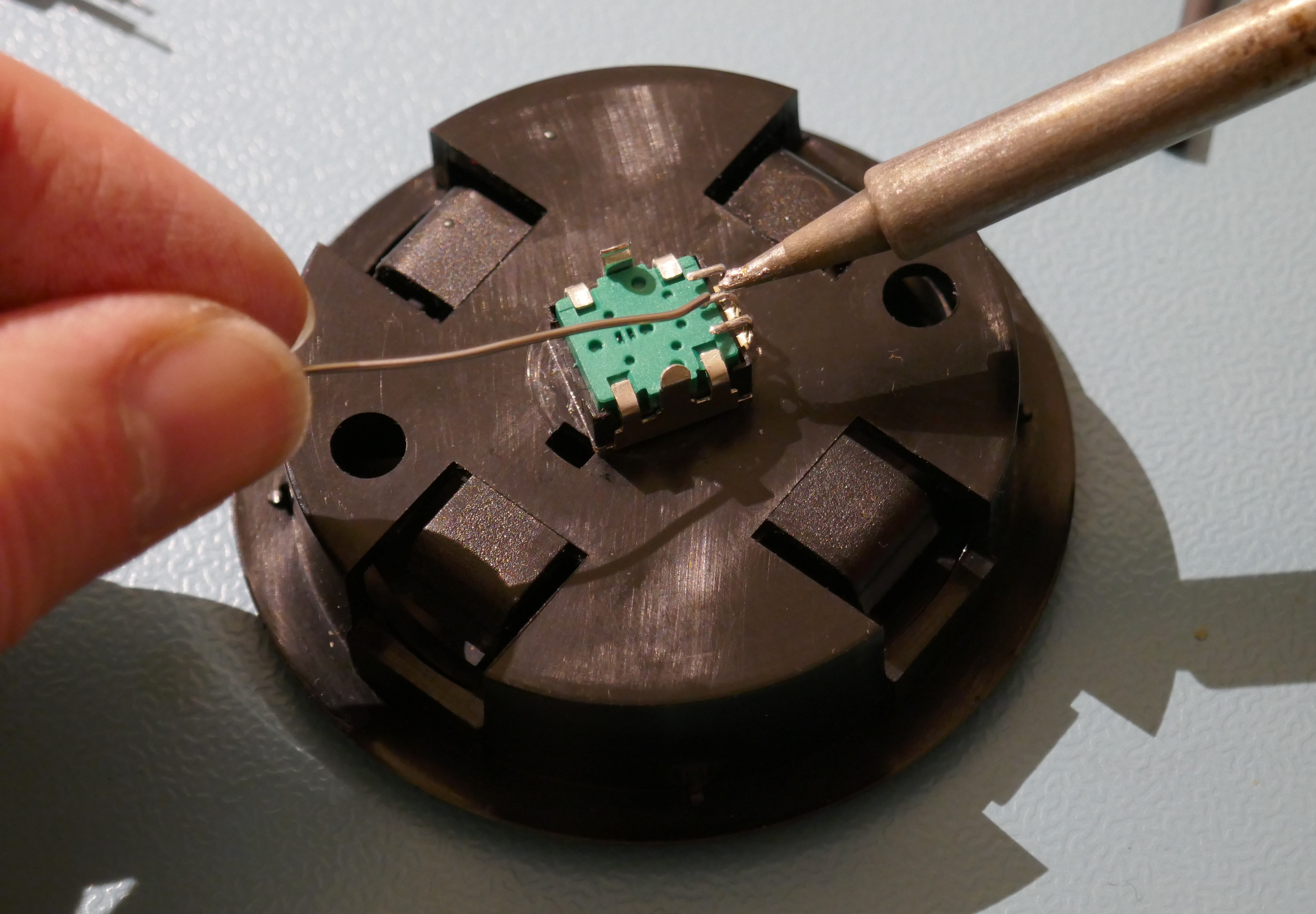
Solder the wires onto the encoder.
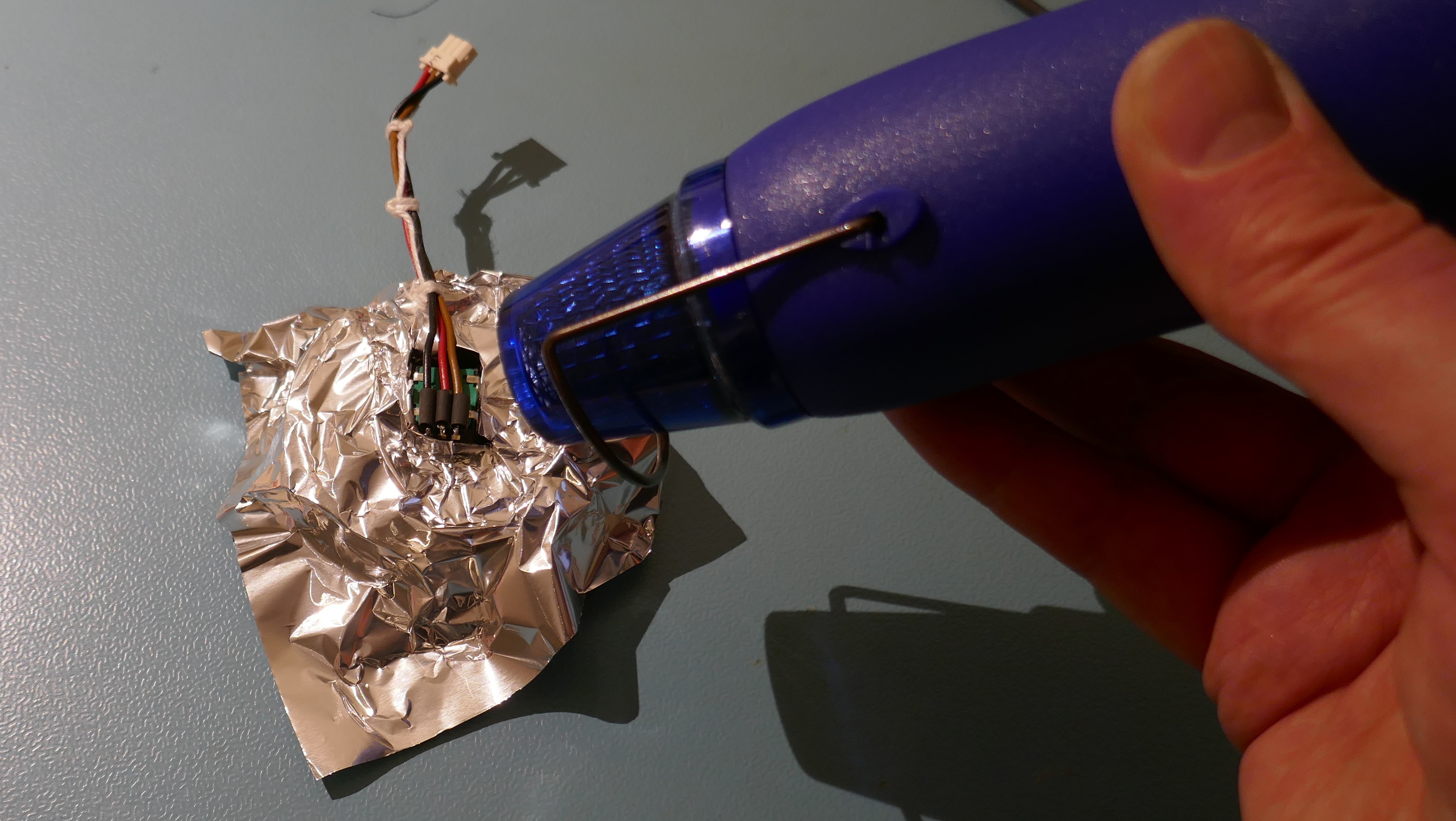
Shrink the sleeve with a heat gun, taking care to protect the plastic by making a heat shield out of foil.
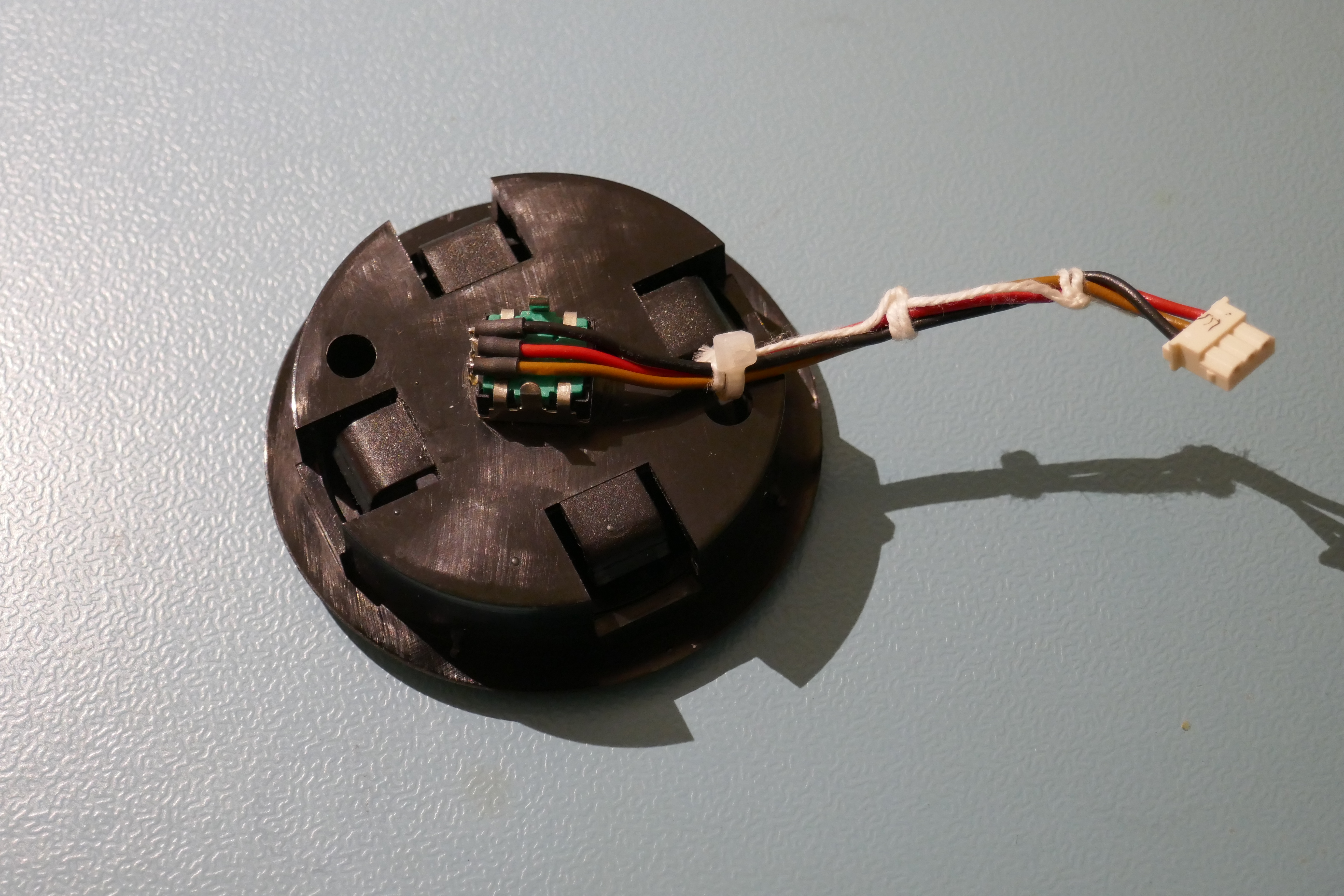
Finally, secure the wire using a cable tie. This is essential to prevent the encoder pins from fracturing, particularly when the assembly & connector is reattached to the front panel.
Reassembly
Place the encoder assembly through the front panel and reattach the connector.
It is a good idea to test the function before pushing the encoder assembly into the front panel with a satisfying “click”.

Fault Finding
If it doesn’t work properly, check that the Red wire is connected to the encoder “common” connection, i.e the middle pin.
If it works backwards, the Signal A & B wires are the wrong way round.
Using A Detented Encoder
Many people ask if detented encoders work in the SuperJX, they can…..kind of….. but there are limitations.
Many menus and values in the SuperJX require multiple encoder “pulses” before changing by “one” increment/decrement. So if using a detented encoder, don’t expect the value or menu item to change on every detent position. This is a limitation of the firmware and the method used to read the encoder. A good reason why the detented encoder type was not selected for the SuperJX in the design.
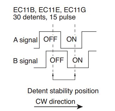
A detented encoder on the SuperJX needs to have the same timing signal output as shown below, others will not work because the firmware/hardware “polls” the signals and doesn’t read pulse transitions using “interrupts” like on modern instruments. The SuperJX requires two stability positions, so odd detents have both outputs high and even detents have both outputs low.
Copyright © 2017 Super Synth Projects, Guy Wilkinson

You must be logged in to post a comment.