This page shows how to build the adaptors and cable for the Roland U-20 and JD-800. For the U-20, it is essential and is used in this installation guide. For the JD-800 it is optional and can be applied if the white flat cable used to connect the motherboard to the keyboard assembly is damaged or missing.
When using a 30 way IDC cable method, the transition board needs to have a 30 way IDC cable header fitted instead, it is attached on the same side as where the mounting bracket locates onto.
Please request the blank adaptor PCBs when ordering a flexible PCB.
These modifications require advanced soldering skills and tools.
U-20 Adaptor PCB
This adaptor translates the two FPC connector positions CN1 and CN2 on a U-20 main board, to a 30 way IDC connector so that it can connect to the new transition board at the keyboard assembly. It is a much more convenient method than hard wiring.
Parts needed
- 30 way IDC Connector header (Amphenol T812130A101CEU 30 way box header right angle, Farnell: 2215255)
- Double row header strip (Harwin M20-9983645 2 x 36 way straight pin, Farnell: 1022243)
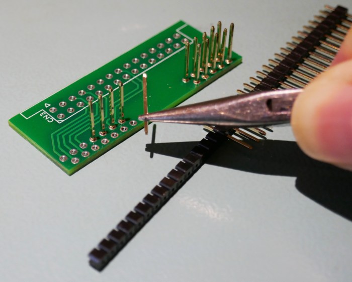
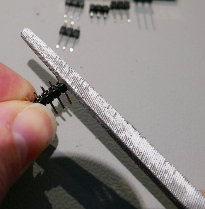
The pins are pulled out from a dual or single row header using small pliers. It is essential not to bend the pins and keep them straight whilst removing them from their carrier.
The picture shows single row header, these were ok but a little tight. Double row header part number M20-9983645 were a easier fit. Pin size should be 0.6mm square.
You may find the pins a tight fit, this is for good reason. The hole diameter of the PCB is exactly the same as the hole diameter for the FPC connectors in the U-20 main board. This means that the pins will remain vertical and if they don’t fit very well, they will be difficult to insert into the main board.
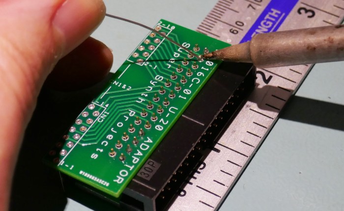
Before soldering, ensure that the pins are all vertical and evenly spaced.
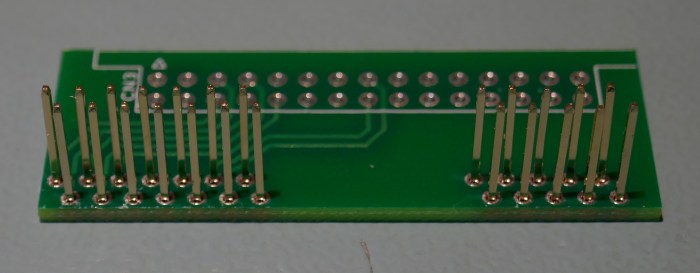
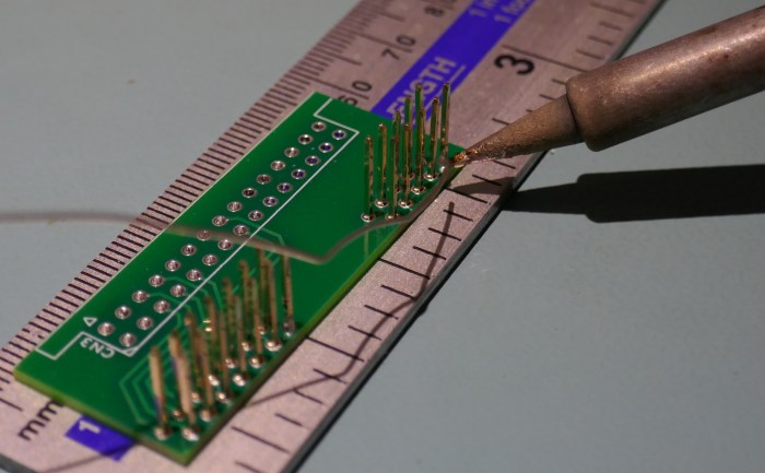
Solder the pins in place, a metal ruler was used to protect the bench from burning.
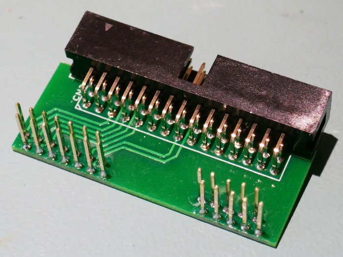
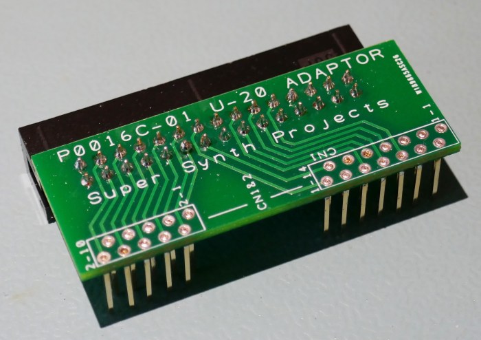
Fit the 30 way IDC connector header.
It’s done and should look something like picture below.
IDC Cable
The IDC cable length is the same for both U-20 and JD-800 adaptations. It is an overall length of 350 to 370 mm when strain relief is accommodated. The example shown was 360 mm.
Parts Needed
- 2 x IDC Cable Mount header Amphenol T812130A101CEU
- 1 x 390 mm long 30 Way IDC cable, 30mm added for strain reliefs
We used 34 way IDC cable and removed 4 wires. For example: 3M Ribbon Cable, 34 Core, 28 AWG, 0.072 mm² Farnell: 297355.
First assemble and crimp the connectors as shown in picture below. Bumps face inward, one connector up and one down. Red stripe to pin 1 marked as a triangle or “V” on connector.
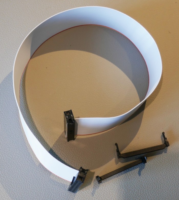
Attach the strain relief clips, the location bump now faces outward as shown in picture below.

JD-800 Flat Cable Replacement
The white flat cable can be easily damaged in the JD-800, this is a tried and tested low cost solution that also provides a suitable mount for an aftertouch gain trimmer. The assembly uses the same IDC cable as shown on this page.
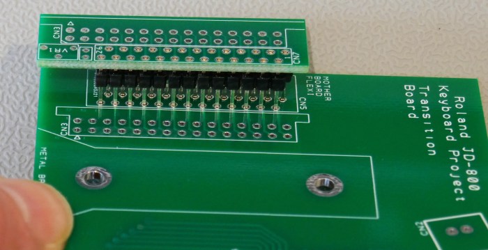
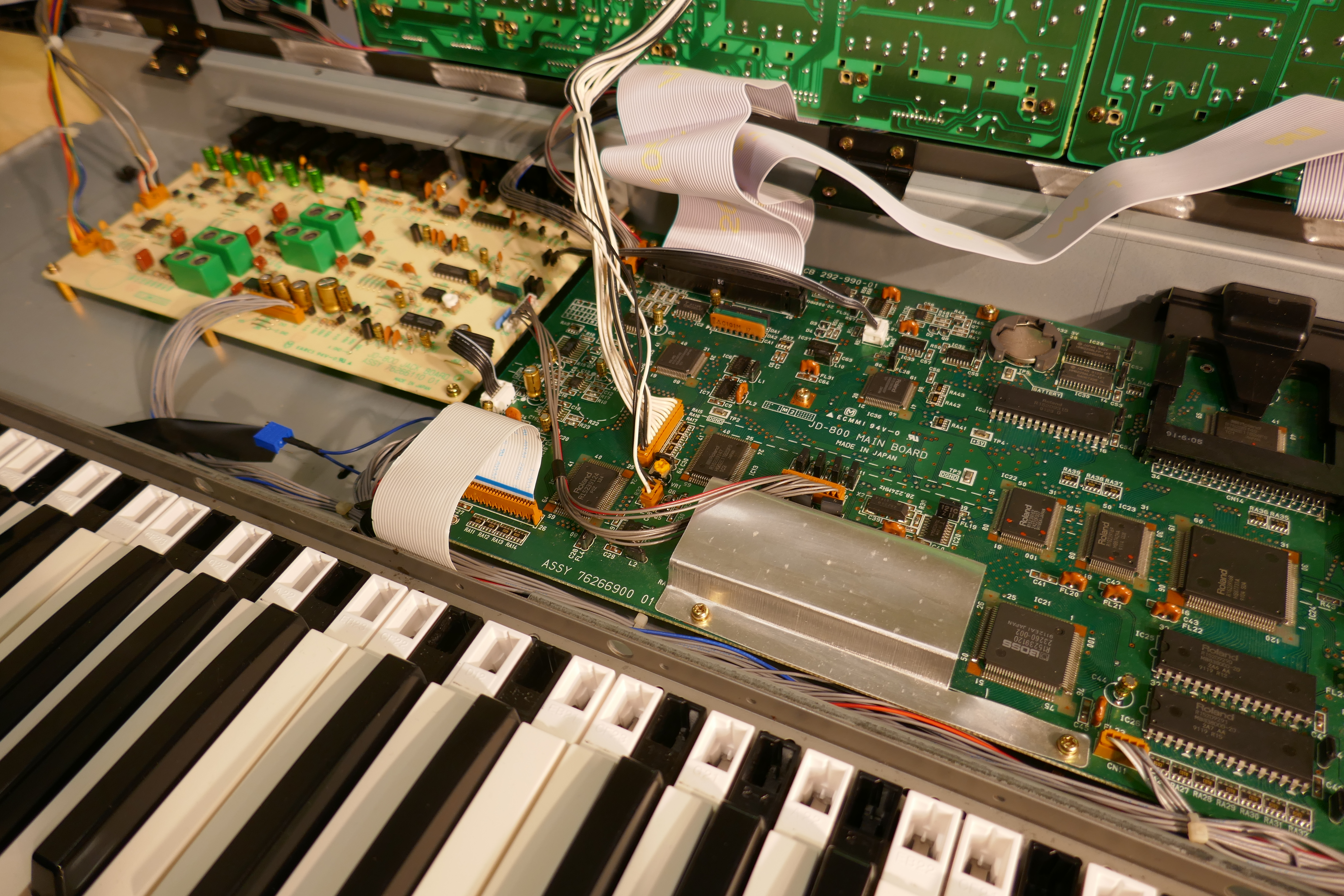
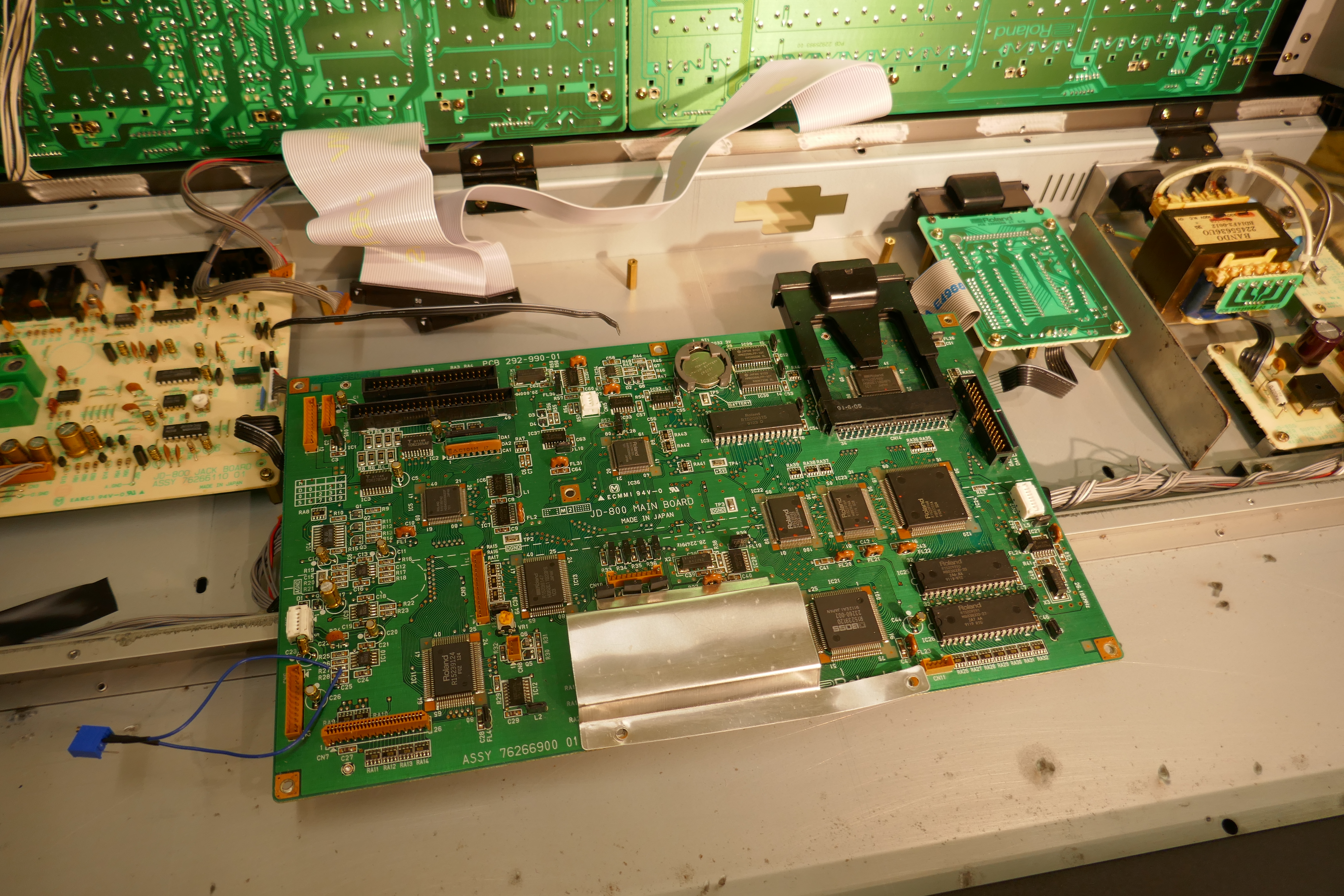
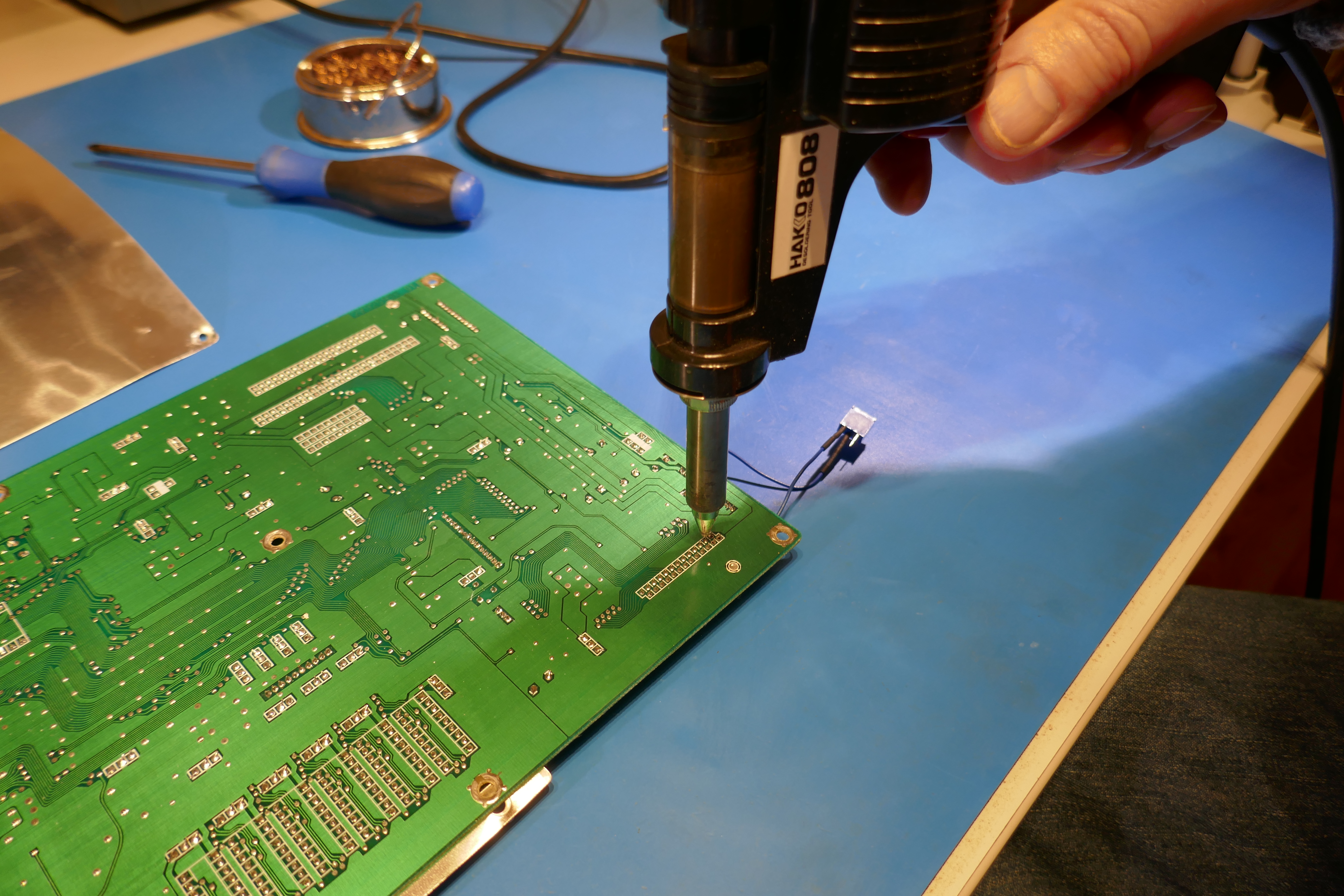
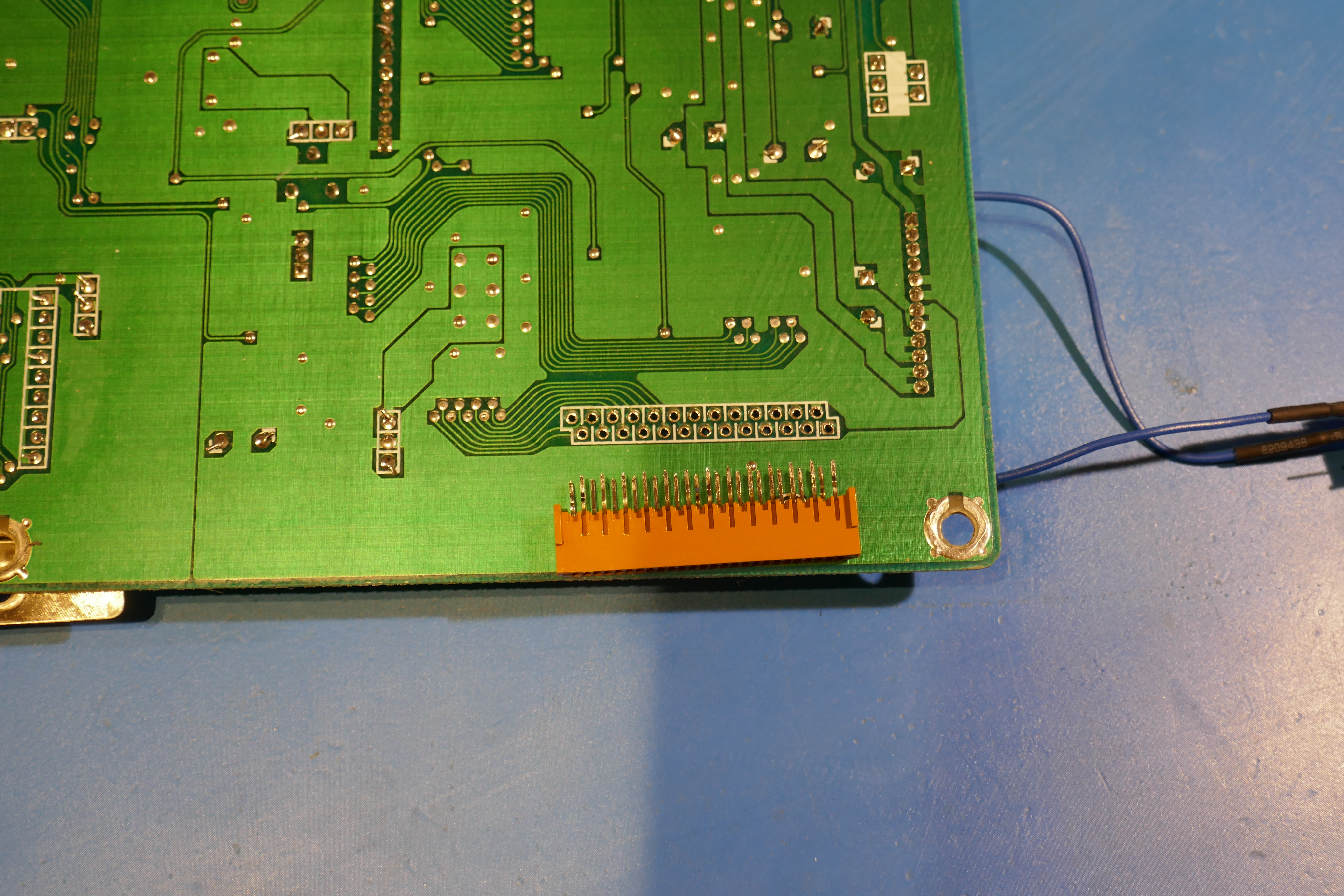
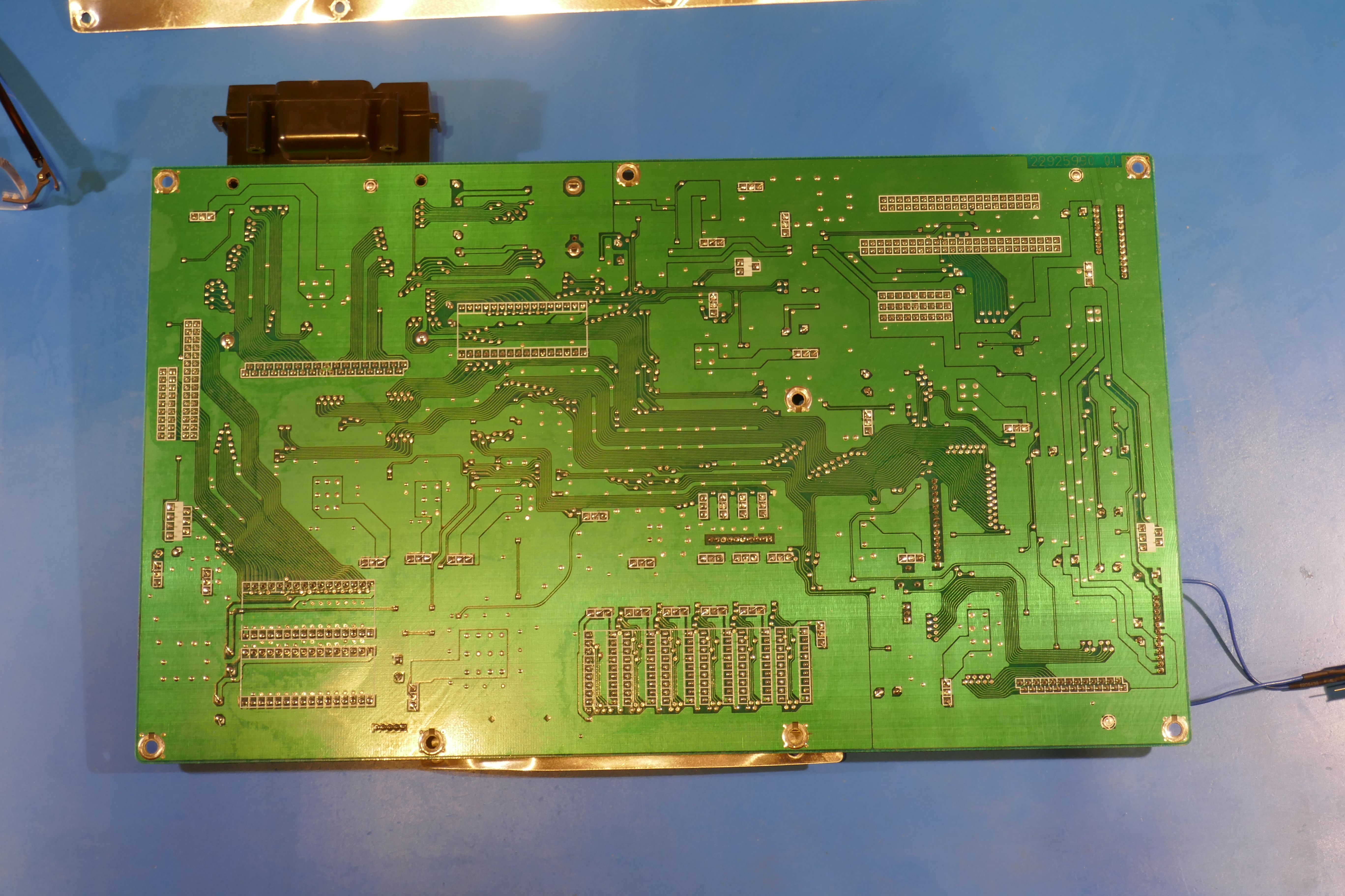
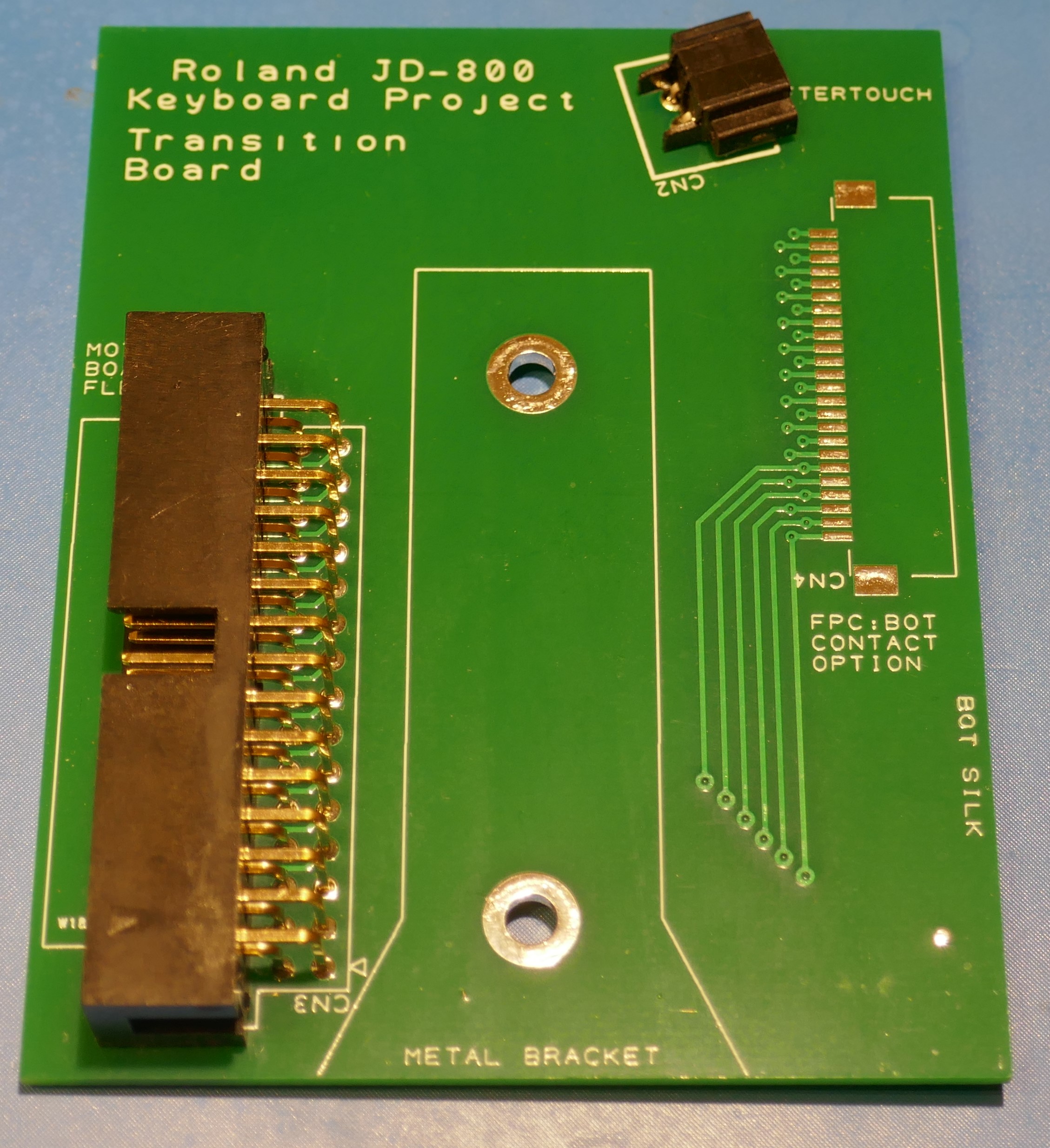
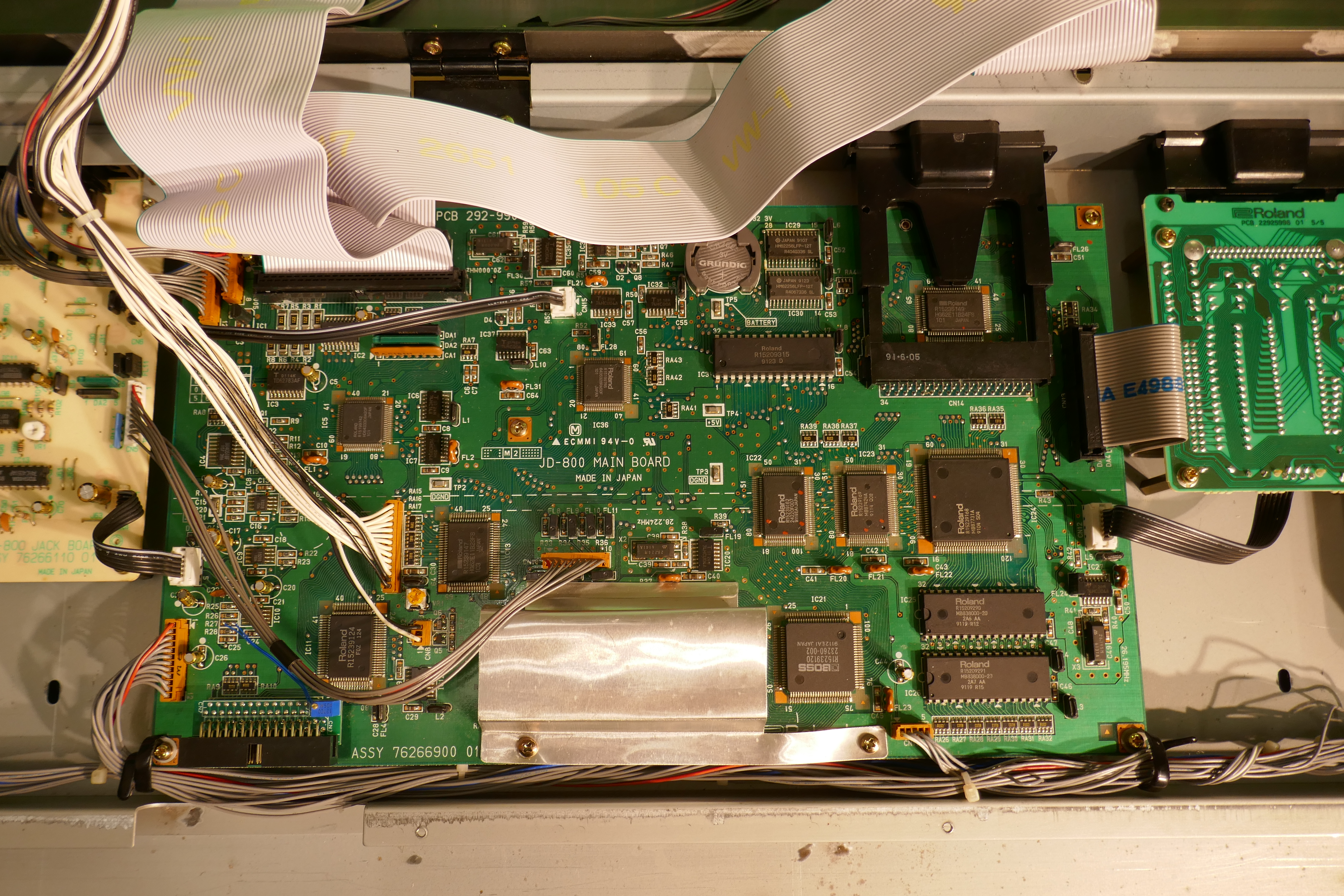
The JD-800 main board is removed and the keyboard connector desoldered and replaced with an adaptor PCB as shown below.
Parts Needed
- 30 way IDC Connector header (Amphenol T812130A101CEU 30 way box header right angle, Farnell: 2215255)
- Single row pin header (Harwin M20-9993645 1 x 36 way, Farnell: 1022263)
- 500K ohm multiturn trimmer potentiometer Bourns 12 turn 500K trimmer potentiometer 3266W-1-504LF
- Adaptor PCB, available on request, free of charge with a replacement flexible PCB
A single row header, pitch 2.54mm, is used for the pinning.
It is unfortunately not 2.50mm as needed by the old header pin spacing. This means that the pins have to be broken off in groups of 2 and 3, then filed to allow them to be spaced properly. The hole diameters of the connector positions in the main board PCB are large enough to allow this to work.
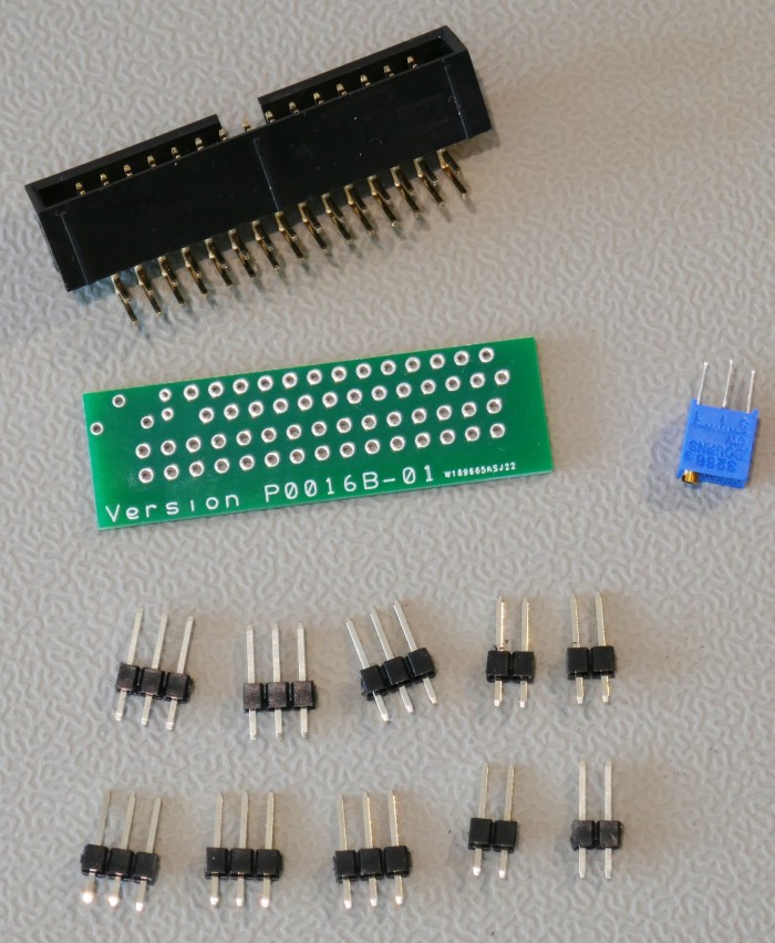
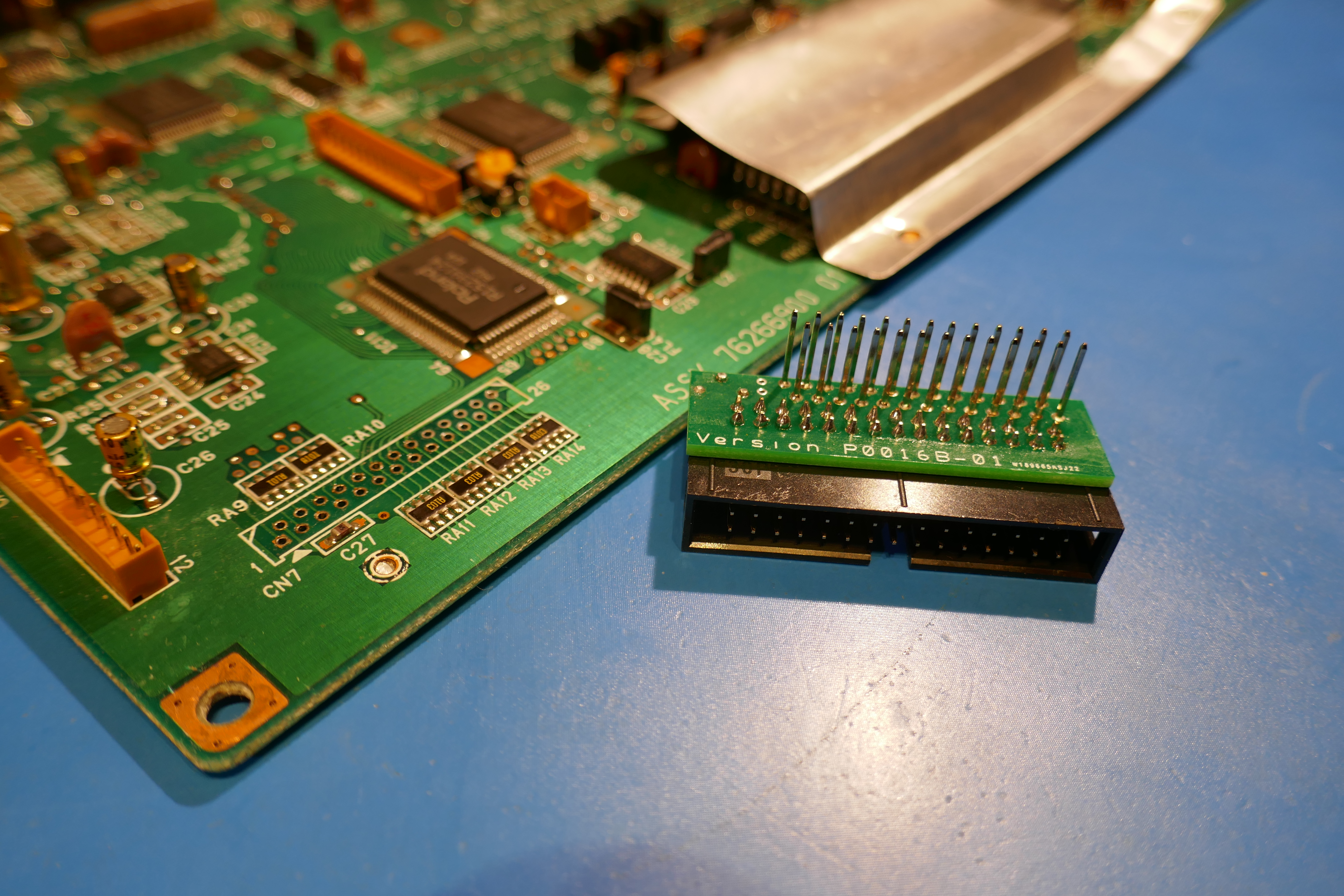
The final set of parts looks like in picture below. For this version we are adding an aftertouch adjustment trimmer too, where two 30 AWG wires will be taken to the correct place on the main board PCB afterwards.
Place the pins in the underside of the PCB.
Space them, so that they allow the PCB to stand clear of the SMD components around the main board connector. Unlike picture below, allow the tips of the pins to stand clear of the pad to facilitate soldering.
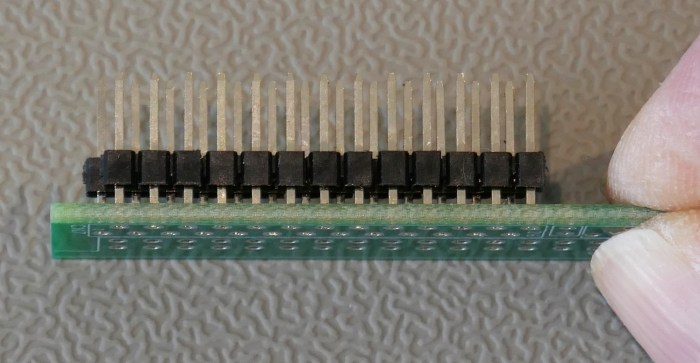
Use the keyboard transition PCB as a pin positioning guide to ensure proper alignment when soldering.
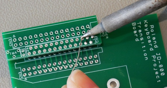
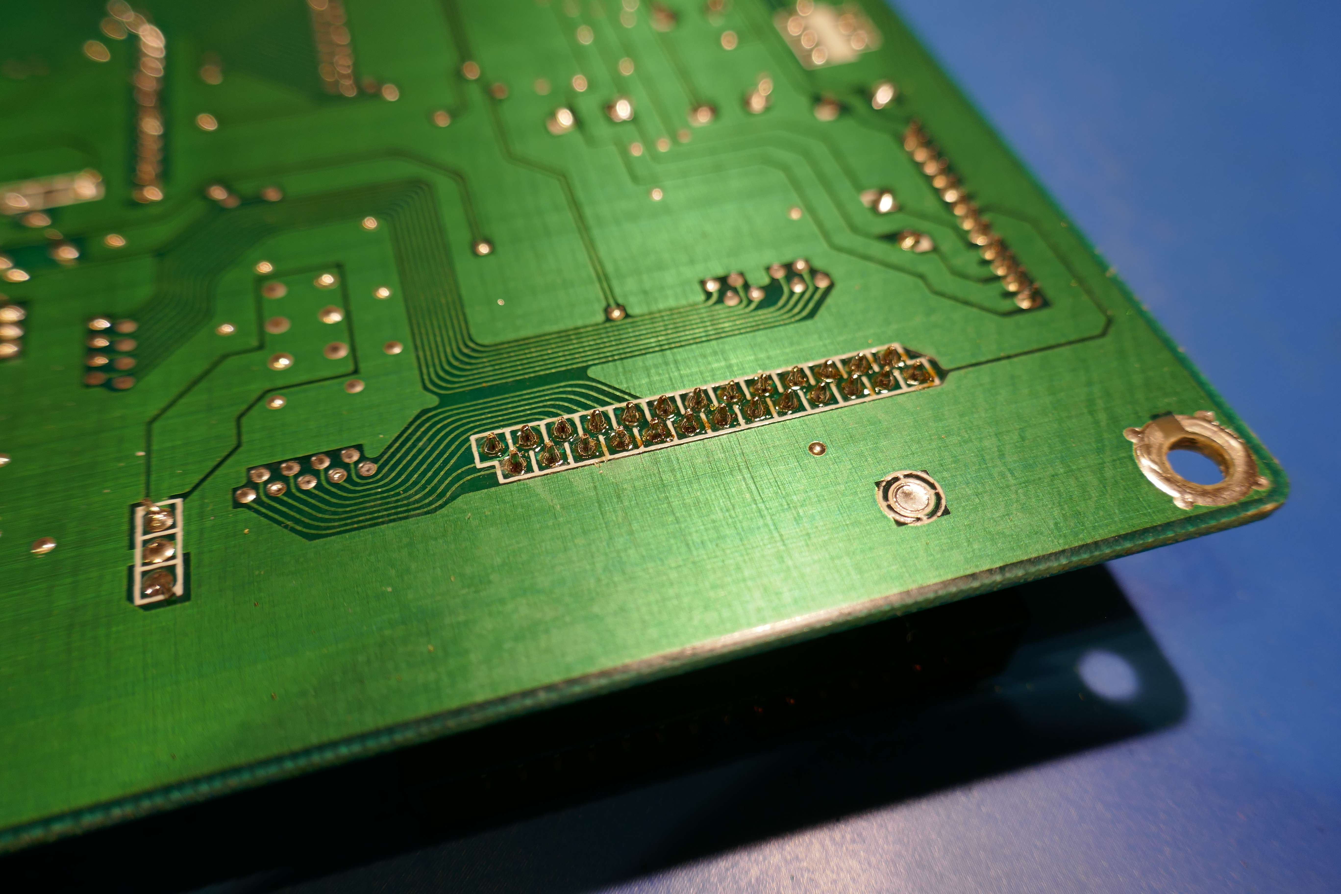
Solder the pins in place, making sure that solder permeates through the hole. The other side can be easily checked for this aspect.
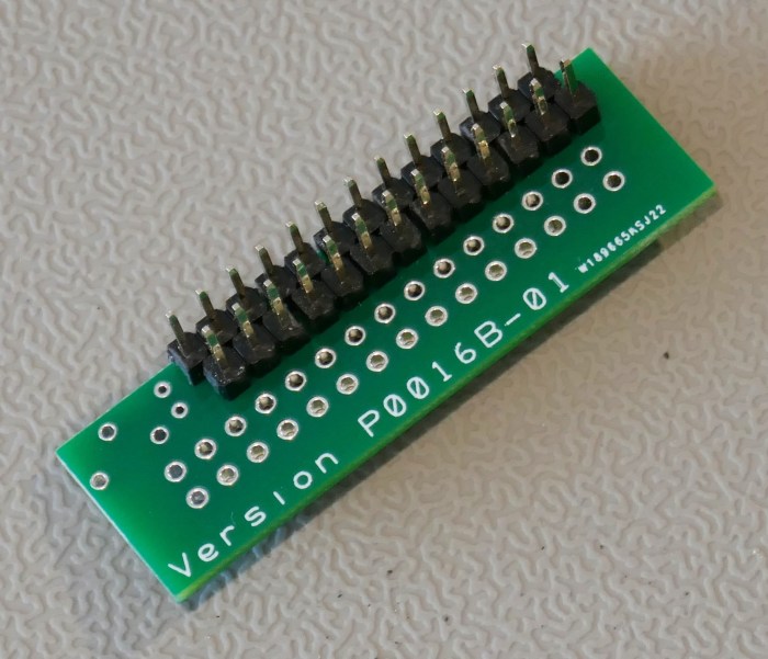
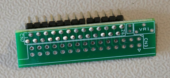
The PCB is removed and should look like the picture below.
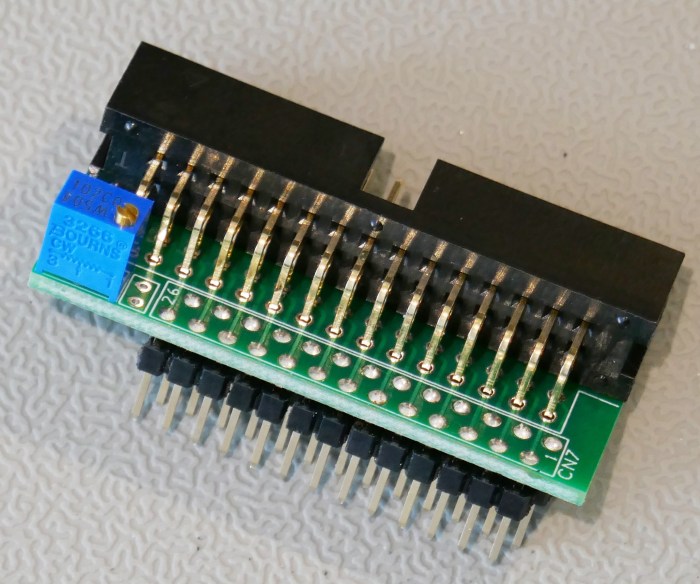
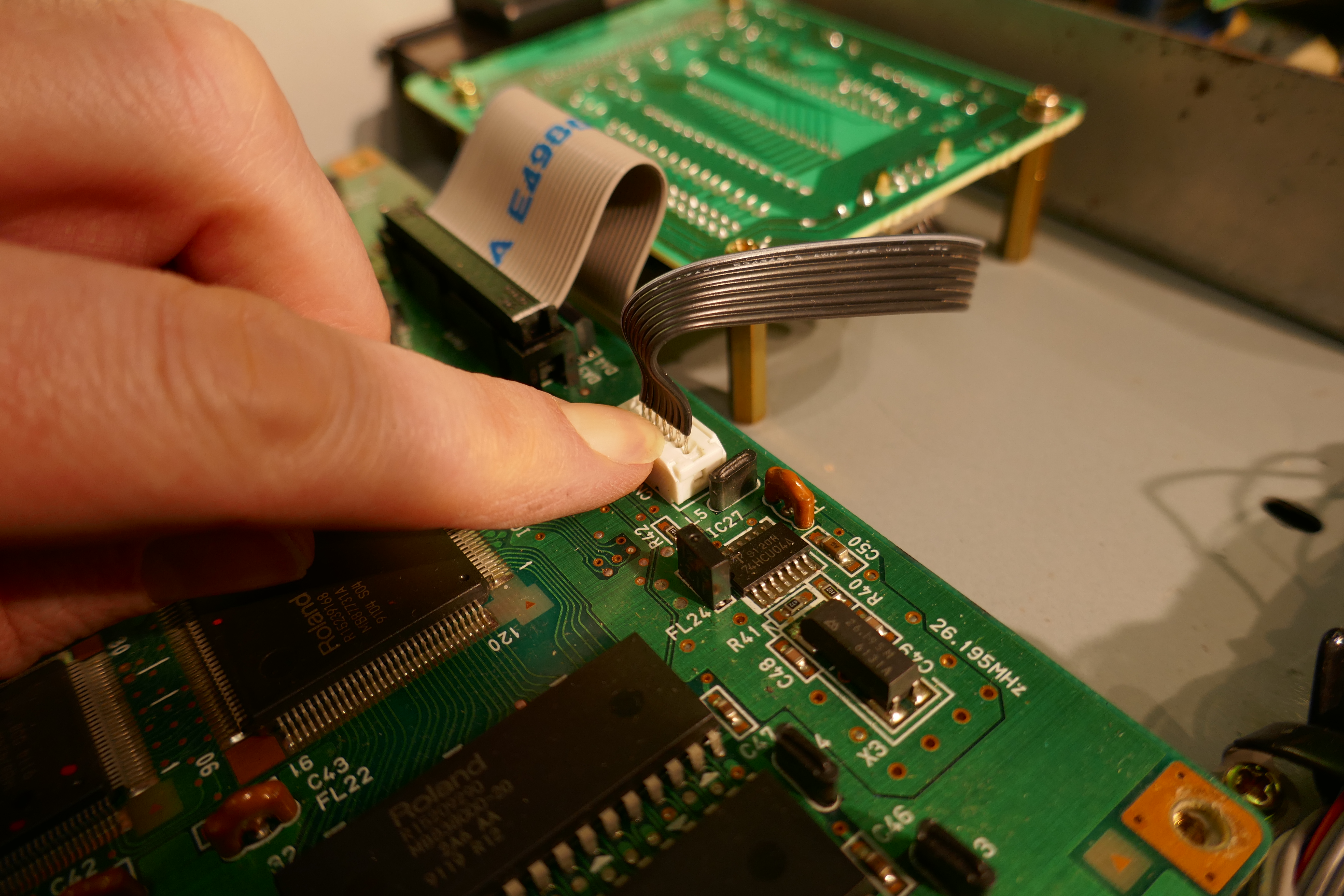
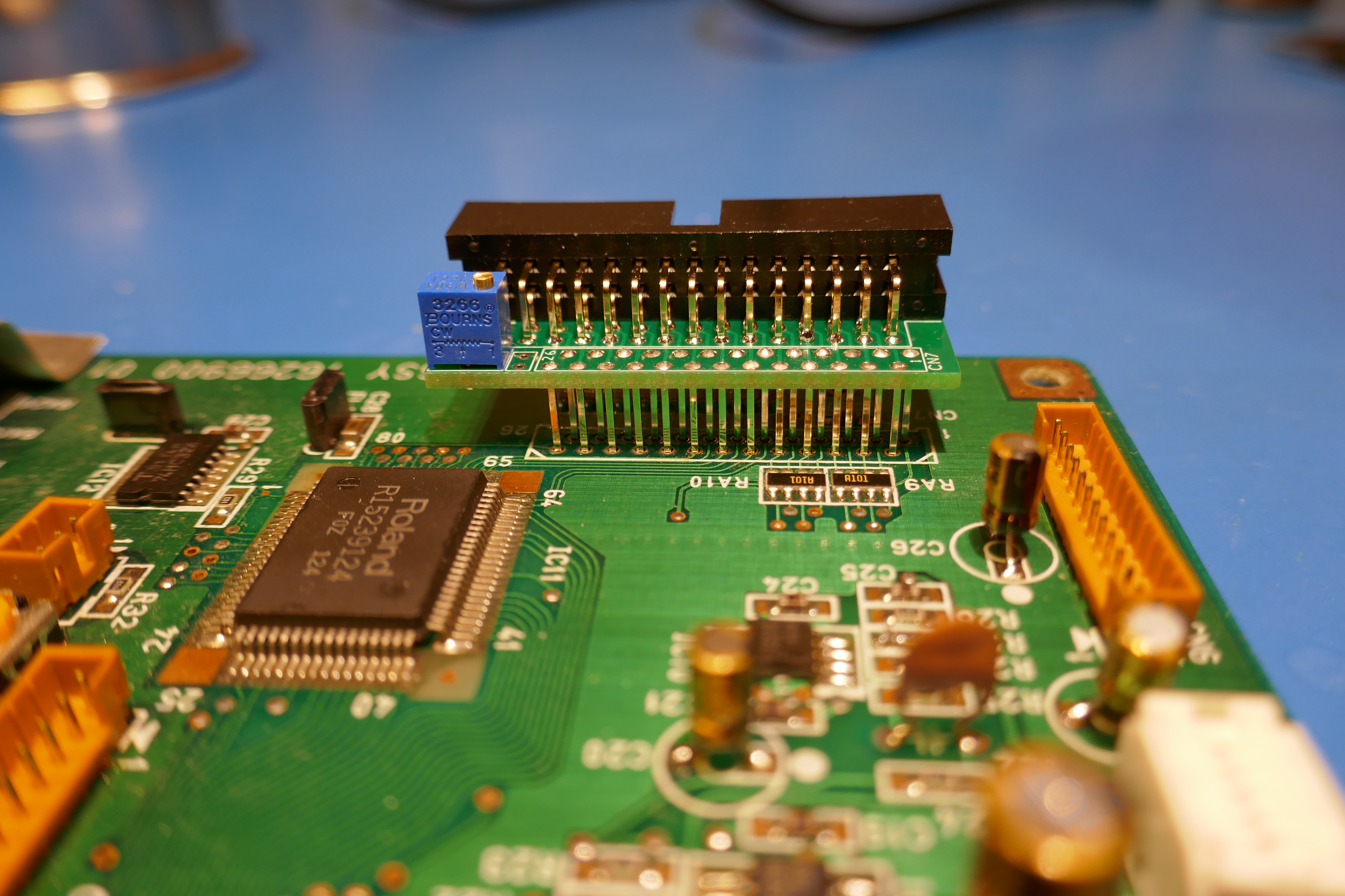
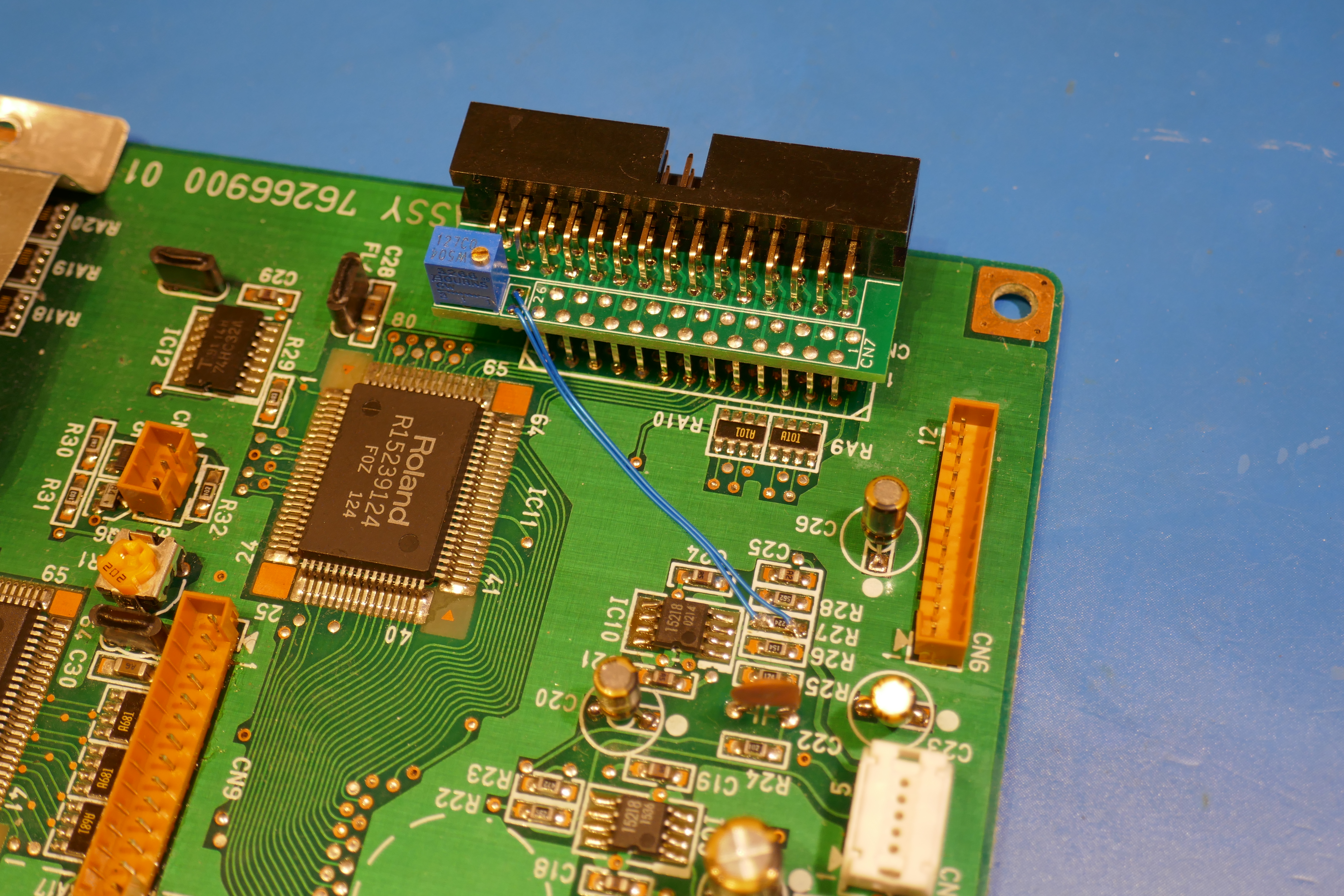
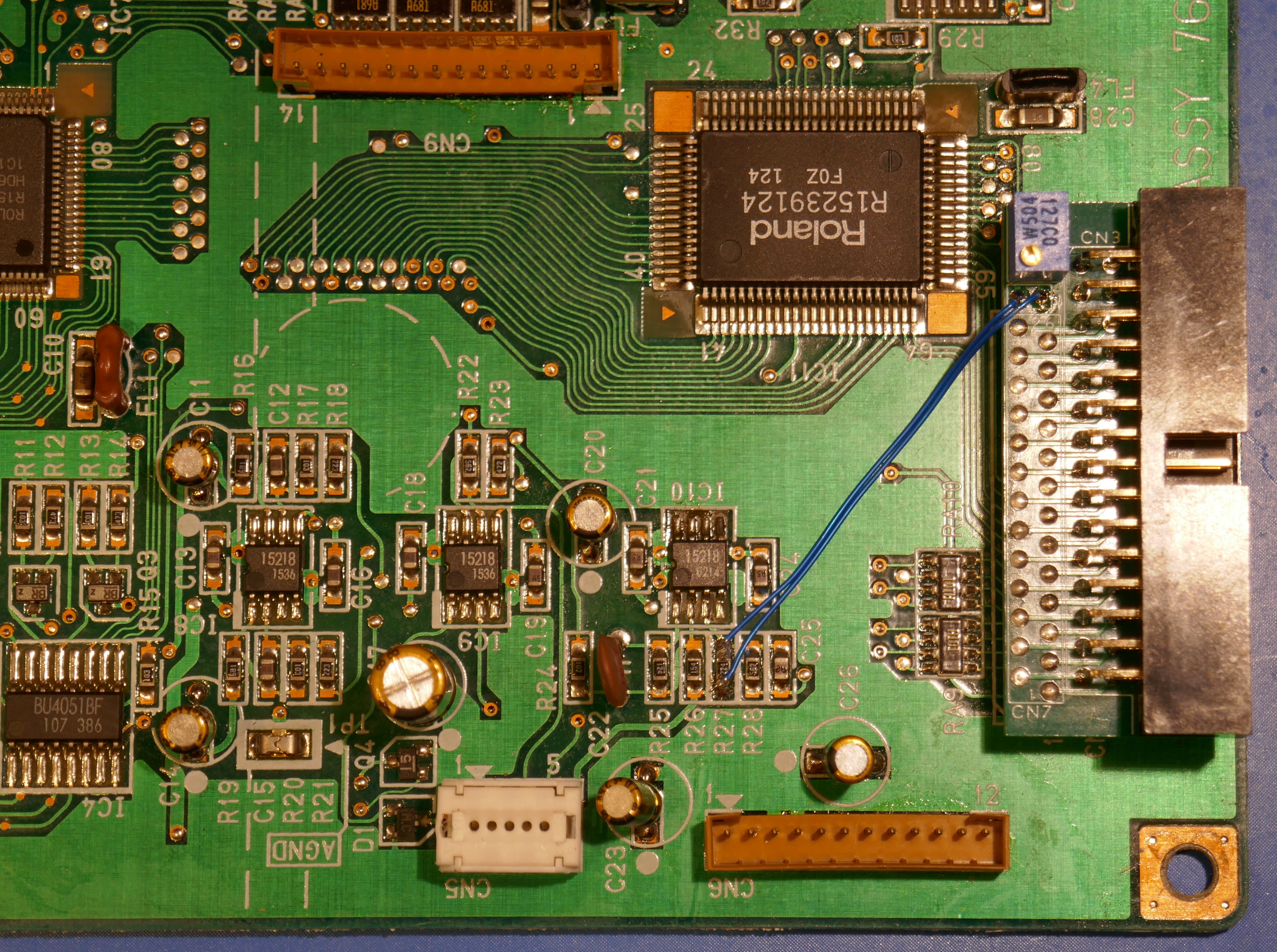
Fit the 30 way IDC header connector and after touch trim pot if desired. In our case we preferred to slide off the plastic spacers to make it easier to adjust pin alignment when fitting to the mainboard.
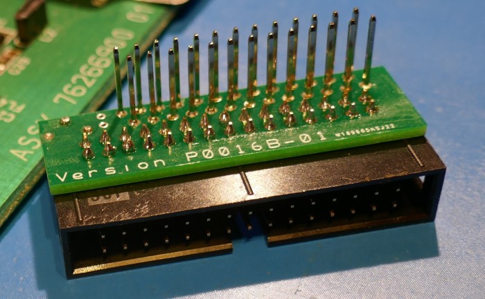
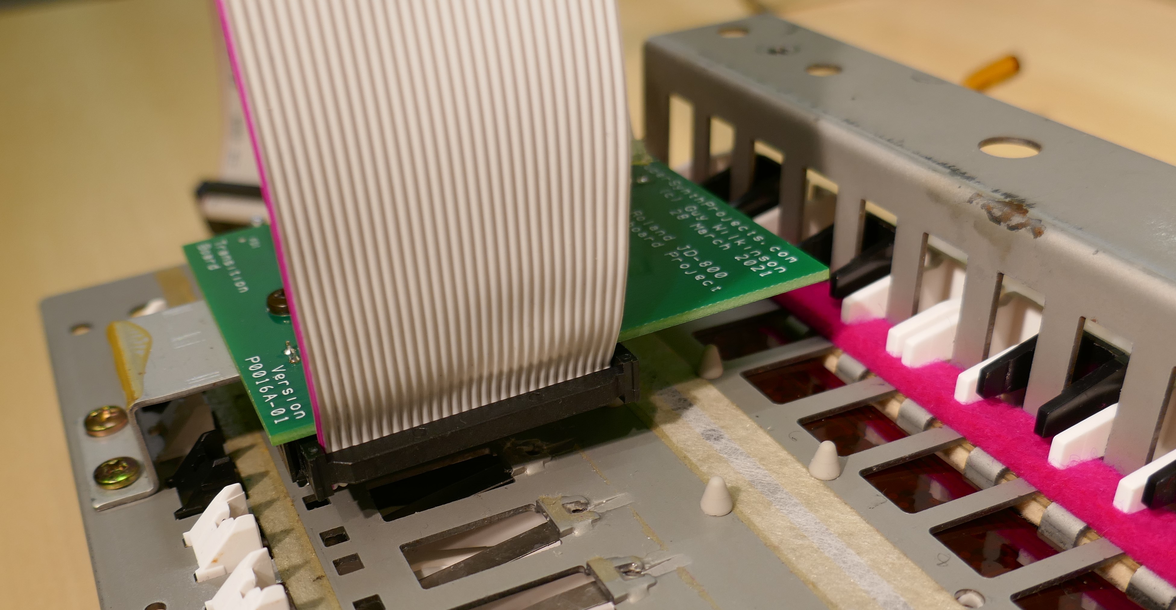
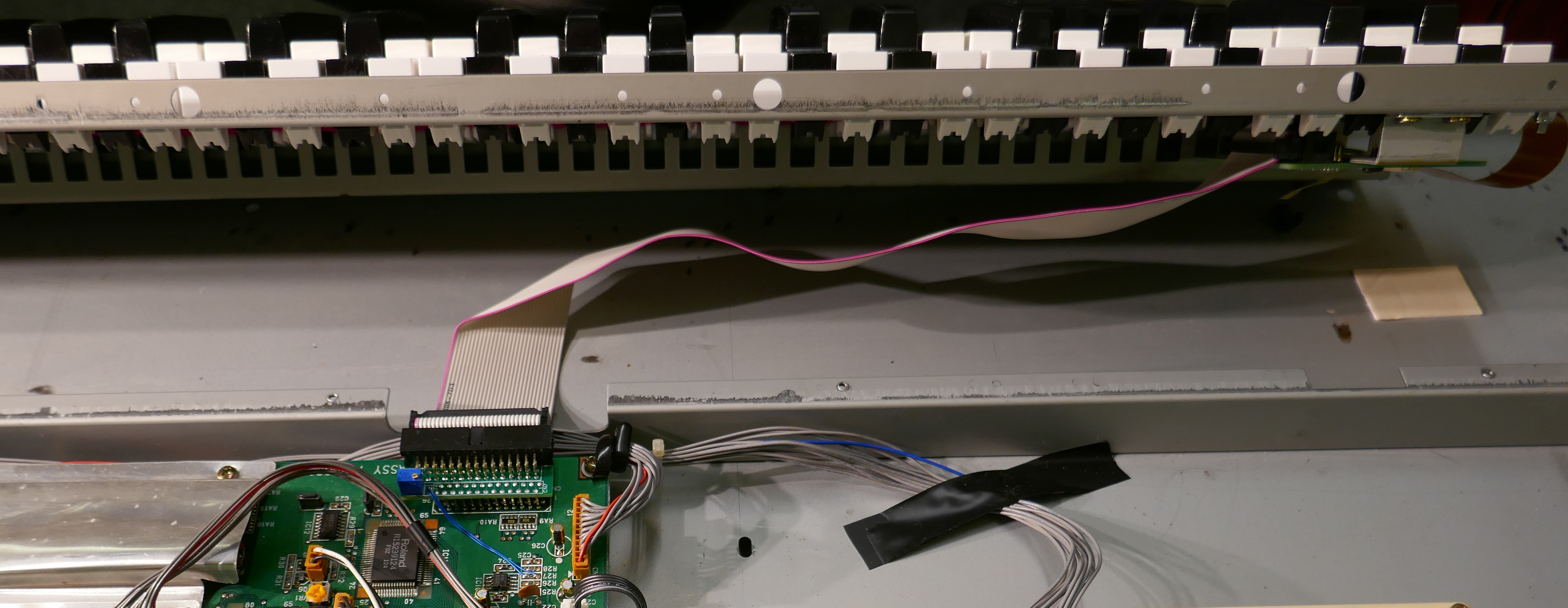
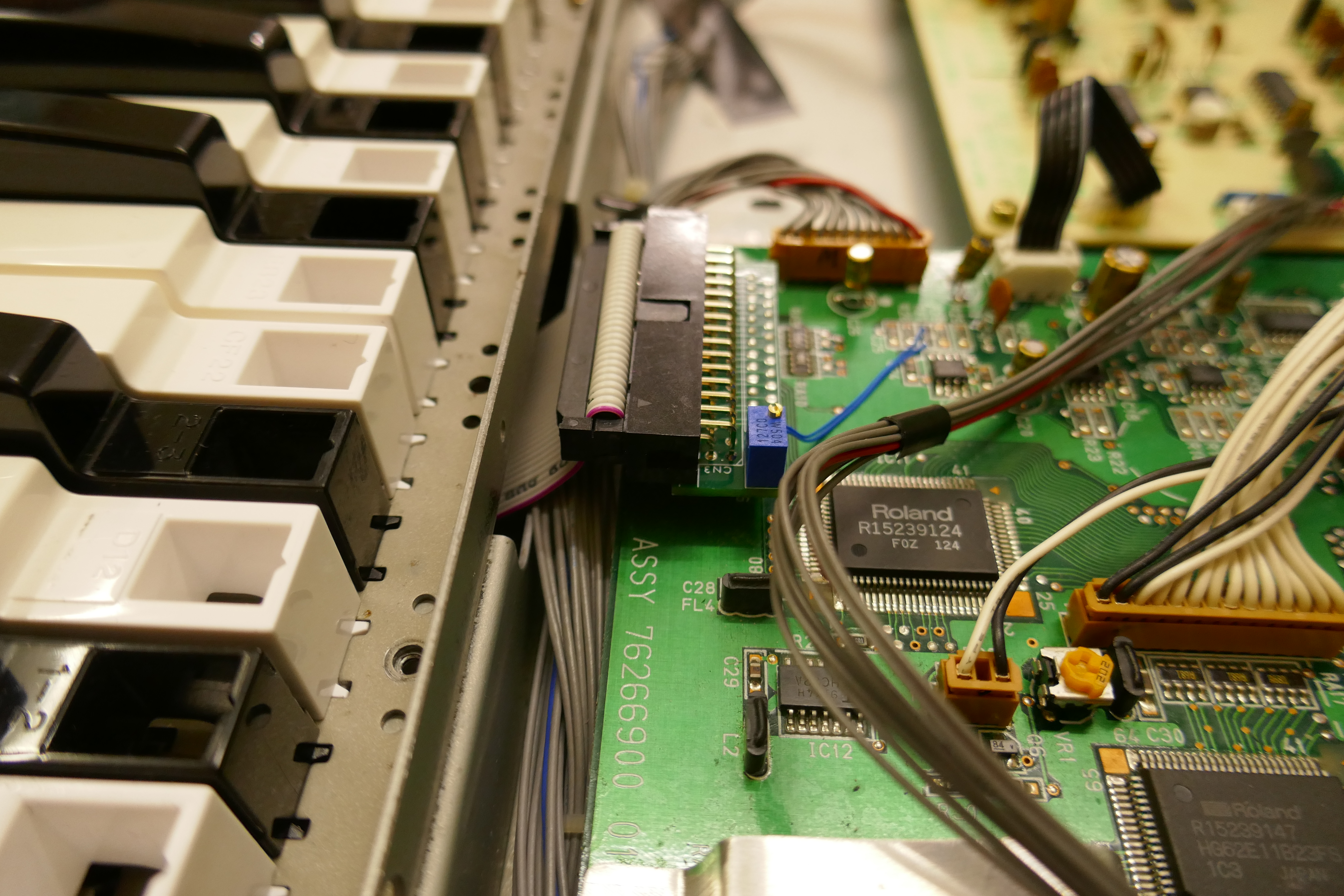
The following set of pictures show the cable adaptor fitted to the mainboard.
Copyright © 2021 Super Synth Projects, Guy Wilkinson

You must be logged in to post a comment.