This article shows a few pictures of my T2000, it’s MIDI interface, an important VCO modification, followed by a detailed instruction on how to calibrate it and get it singing again. I have also put on a few details of resources found on the web to help keep it in shape or repair faults. There are a huge number of YouTube videos showing the capabilities and history of this synth.
Background
I bought my T2000 in 1995 from a music shop in Birmingham for £160 and at first couldn’t believe it was for sale. From a very young age I really wanted to build this kit synthesizer. It was created by Tim Orr, who was one of my childhood heroes because of his rather clever approach to electronics design. This design does not disappoint, he really did squeeze as much as he could out of as few components as possible.

It is very raw indeed, the filter is great, VCO could be a little more polished, but it would take many more components to improve it. A second VCO would be a really cool feature, but in 1978, cost was a factor.
It is in my mind, “purest analogue”. A miracle of electronic minimalism, yet has a full set of flexible controls, almost anything is possible with a little effort. The more I play it and drive it through a MIDI interface, the more I like it………….
Playing The MIDI Blues
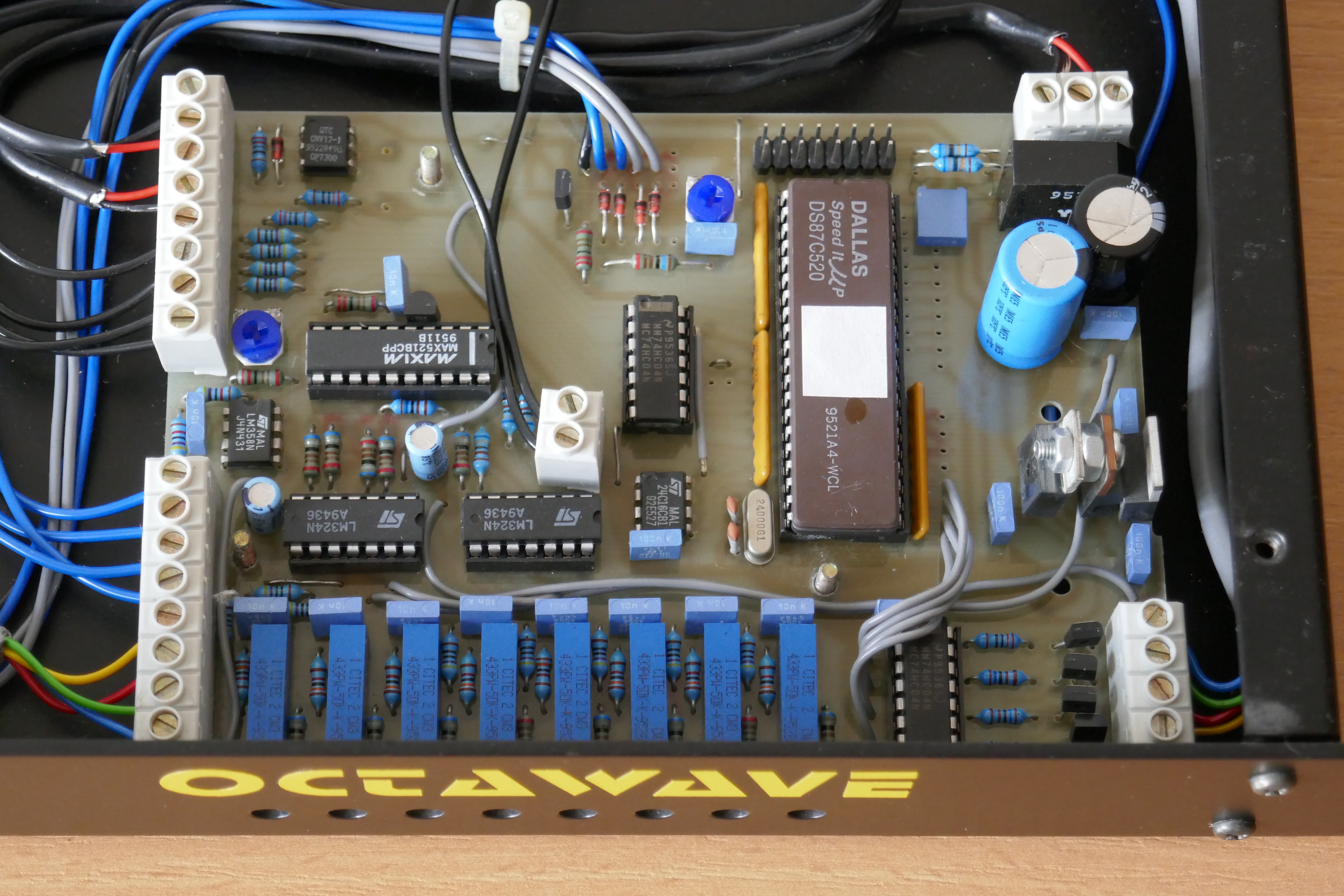
Back in the 90’s, I set to work making the “Octawave”, an 8 channel MIDI interface to control the T2000 and any other analogue synthesizer. This meant that I could use the T2000 in my MIDI set up and sequence it, I did record a track with it too.

It was a 19″ rack unit based on a DS87C520 micro-controller, with code written on a Tasking C51 compiler. The casing and bare PCB were professionally made. In total I made 5 units and had 2 units in my rack set up, only 2 remain to this day. the main board is shown below. I has a number of features including clock management & DIN sync interface used with a drum machine. The main board was also used to MIDIfy my Korg Polysix which still is in use today.
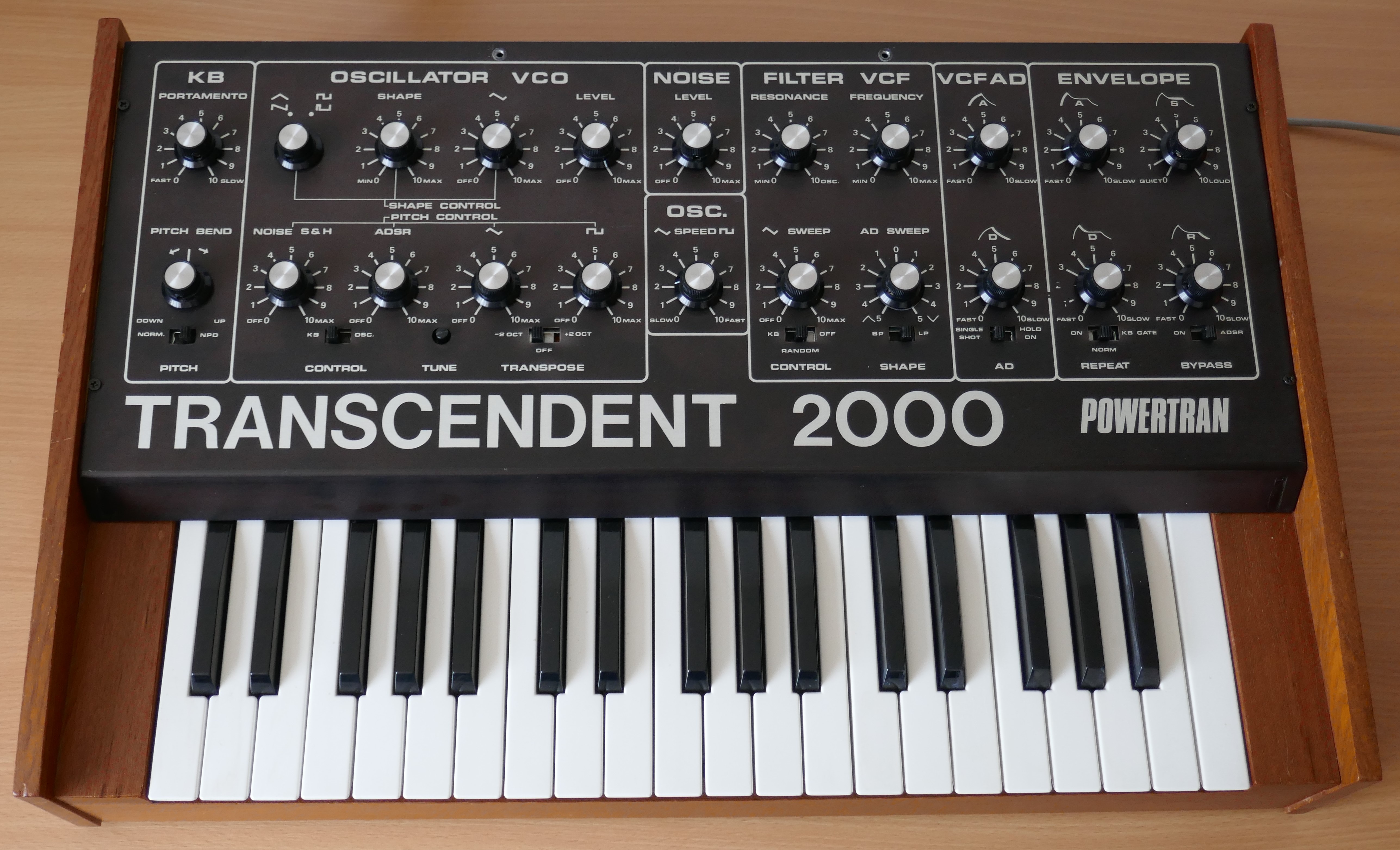
T2000 A Fine Example
This instrument was built exceptionally well and has been very well looked after. The tuning pot needs replacing, because time has impacted the track as the tuning essentially kept the wiper in the same position. Instead I use the pitch bend control to move the tuning during a session. I should get around to replacing it.
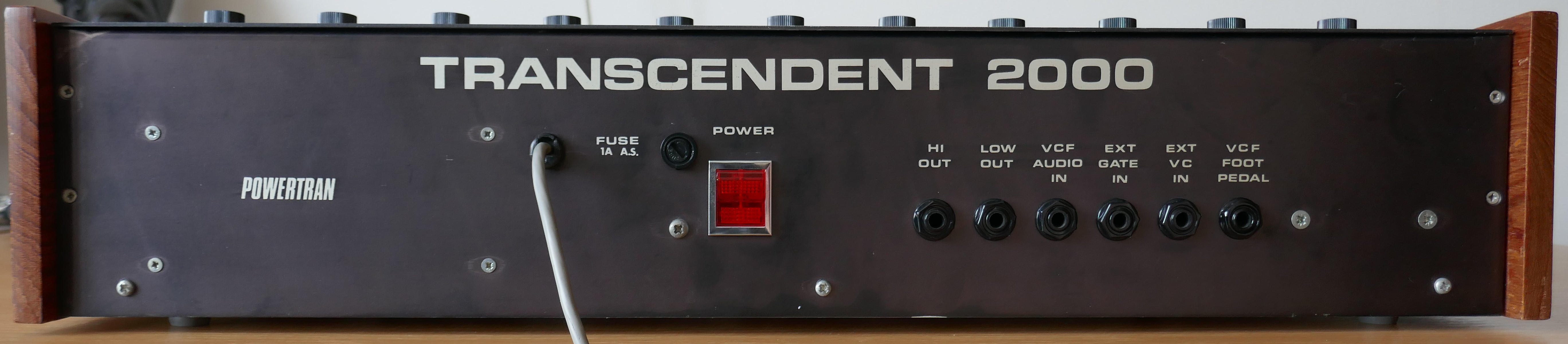
External
The rear view shows a healthy set of sockets. It even has a VCF analogue input for putting other instruments through it, thus when combined with MIDI interface and another digital instrument, some fun can be had. As for comparability with standard CV & gate, there is little, essentially I added an extra PCB with an Opto-Isolator on it to drive the level shifted gate voltage to my interface, then used the trimmers on my interface to adjust the range.
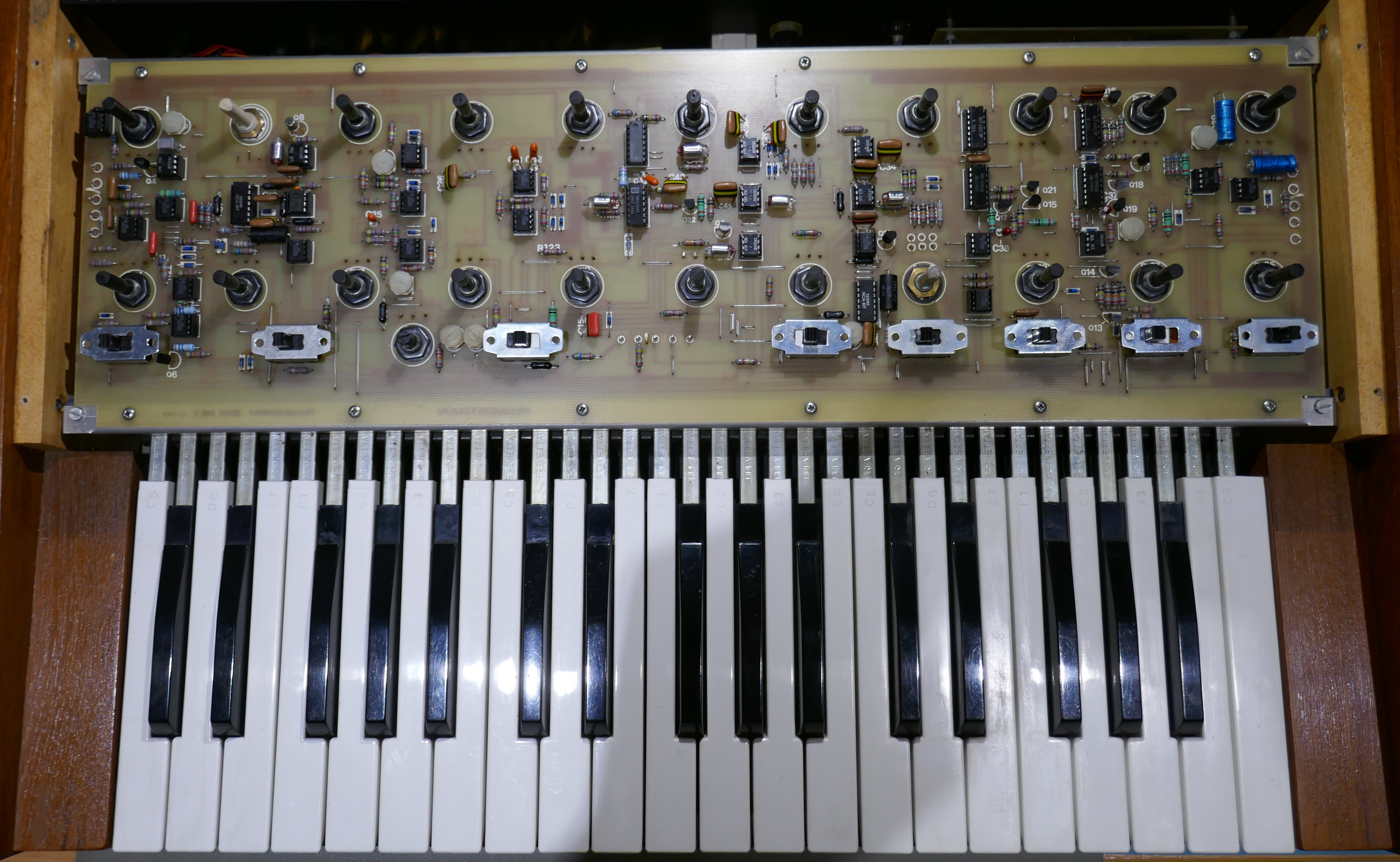
Internal
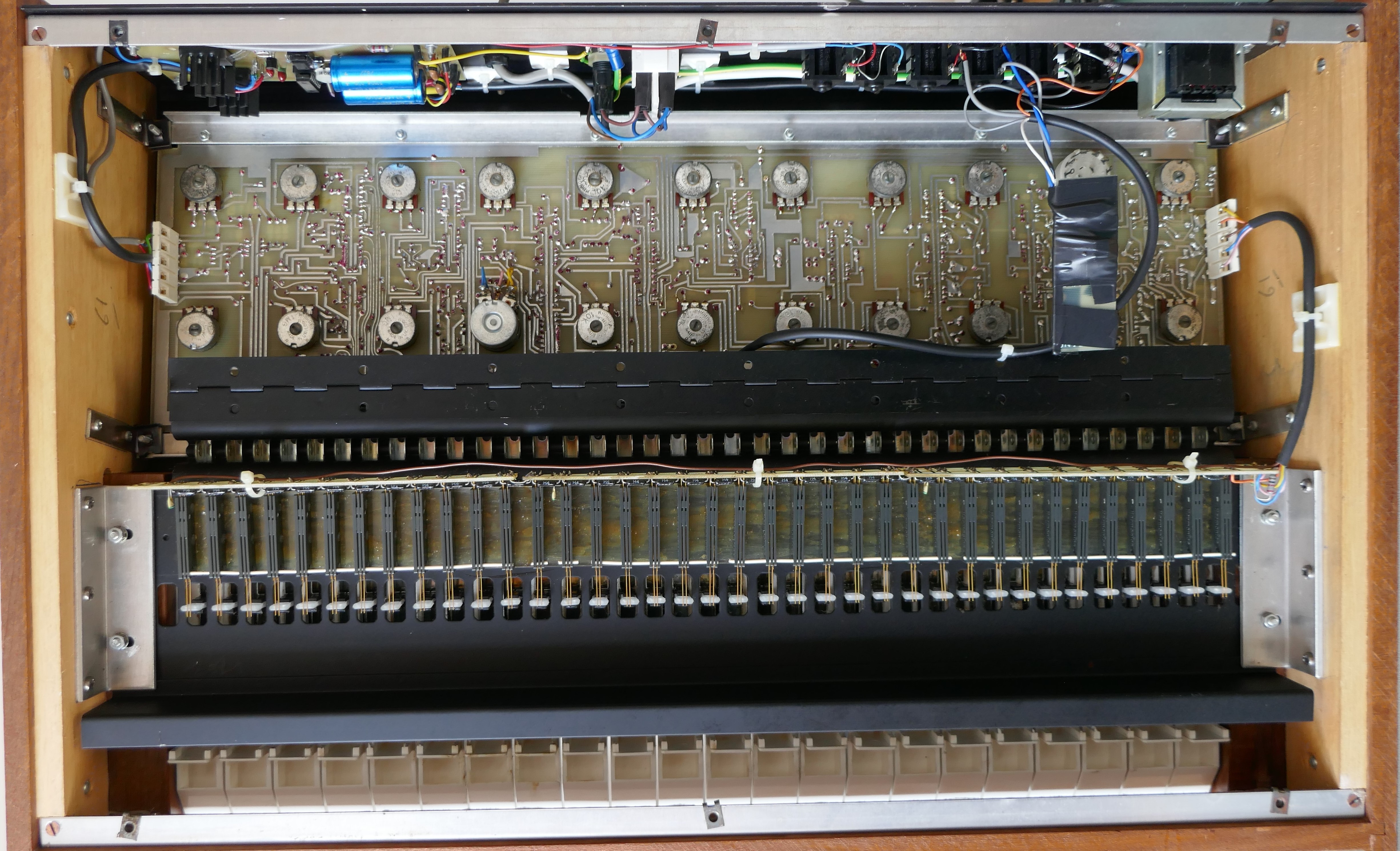
A picture of the internals is shown below with the front panel removed. Luckily unlike many production synths, the knobs have grub screws to fix them, so removing them doesn’t risk damaging the potentiometers.
Internal view with the underside panel removed. I rewired the mains wiring and used shielded multi-core cable for the low voltage AC power. Original mains wires were only 24AWG with 250V rated insulation, a scary prospect for UK mains supply. A 13 amp fuse was changed for a 3 amp too because cable to fuse was rated to 3 amps. All power wires were secured to the panel to minimise loop area with earthed chassis, keeps noise at bay. In the picture the CV Gate interface PCB wrapped in tape can be seen.
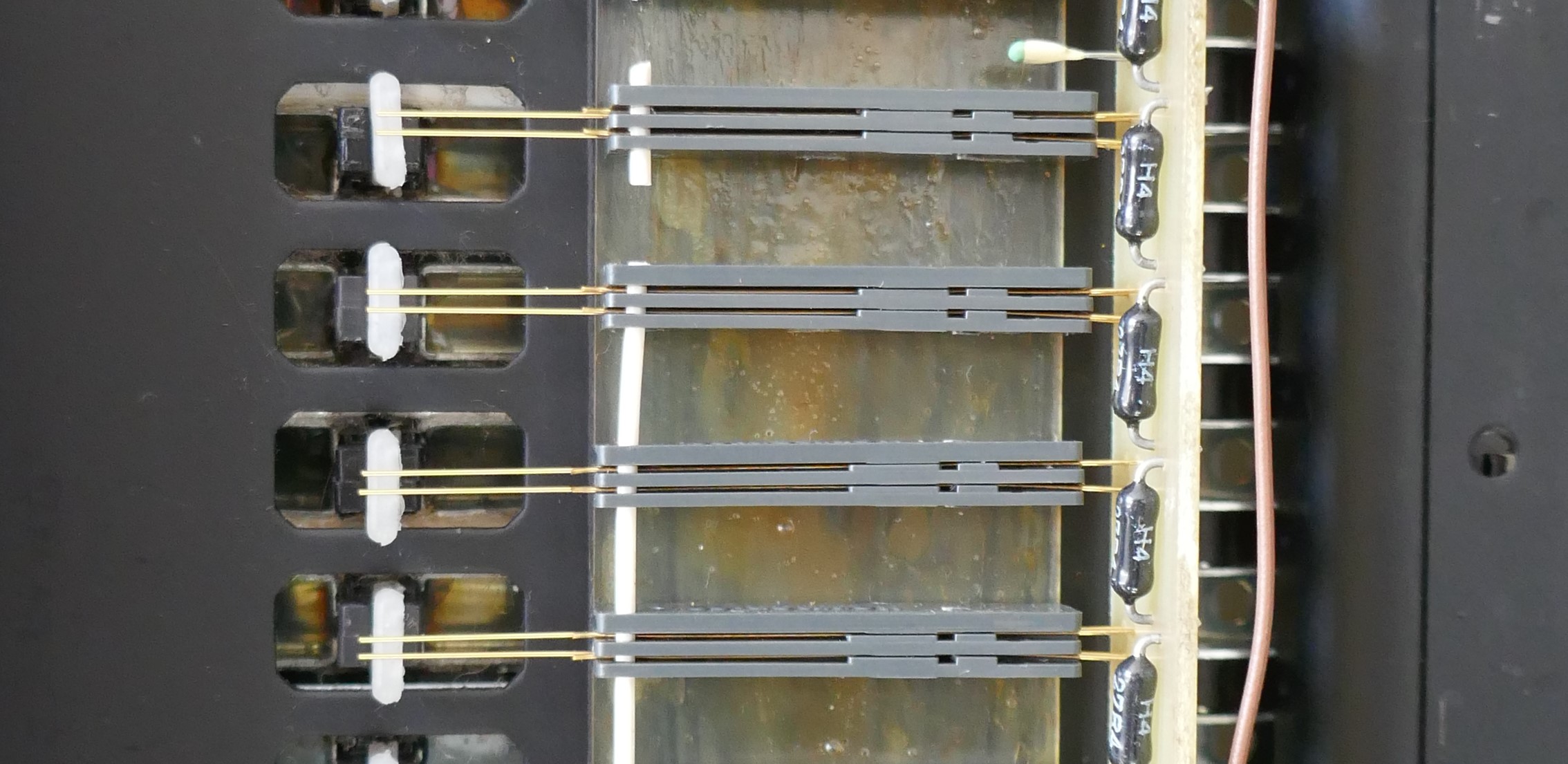
Keyboard contacts are extremely fragile and essentially they are “booby trapped”. The contacts are secured using contact adhesive and the PCB floats freely behind the connections. The glue was still in excellent shape on this instrument. To correct for issues, the previous owner had strung wire insulation through the holes on the sides of contacts to shorten the travel. It certainly works. Note the expensive high precision resistors for the keyboard circuit.
Recommended Modification
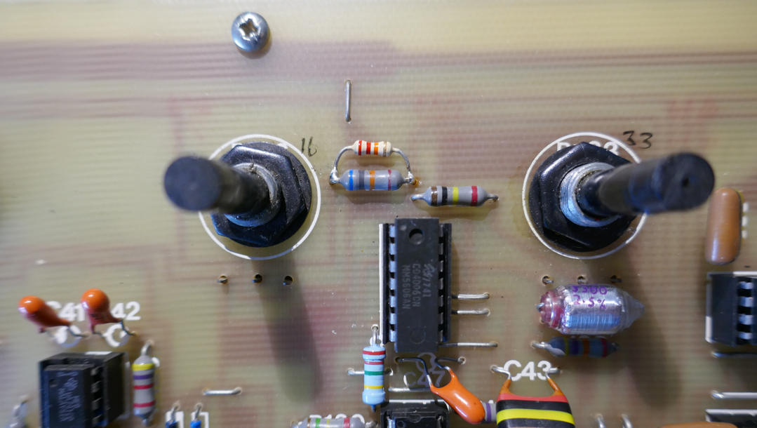
As shown on a YouTube video by Telefunkian, to increase VCO level, it is recommended that R129 68K is reduced to 15K ohms. I did this by adding a 20 or 22K resistor across the 68K. Definitely worthwhile, but if you like a loud noise generator, then that will need adjustment too.
Calibration
An oscilloscope is necessary for some adjustments but most can be achieved by ear or using a frequency counter. An oscilloscope however, allows a proper visualisation of what is going on, so that any issues can be identified quickly.
The control potentiometers get very crackly with age, so calibration may be more tricky than you can imagine. The preset trimmers are not so affected, the ones chosen for the kit were good quality. Often people recommend replacing the presets with multi-turn versions to achieve greater accuracy when setting it up.
This synth is particularly sensitive to temperature, so it is best to let the thing warm up or re-check the keyboard spread and transpose calibrations once completed.
Here is a pdf of a spreadsheet, used to generate the page data below:
PCB Layout
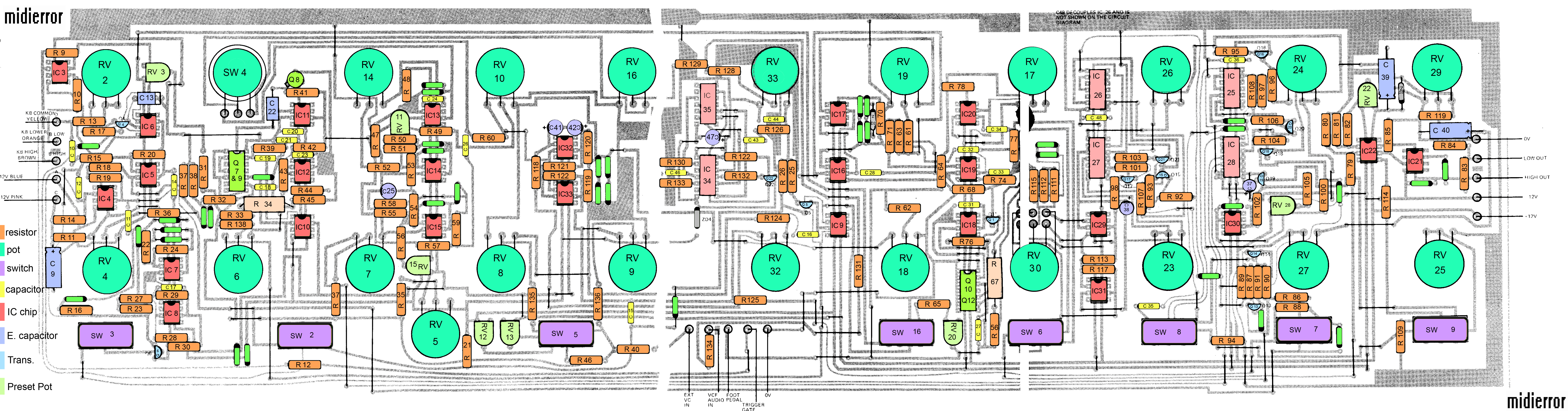
mididerror T2000 page has a fabulous reconstructed layout of the PCB. It is incredibly useful when finding probe points or faults because the Silkscreen on the PCB has references for components, but they are covered when the component is installed! The original magazine article is a tragedy to read, as it is all broken up. Click on thumbnail below to access the layout on midierror site.
Preset Potentiometer Functions
Calibration of the Powertran Transcendent 2000 involves some simple adjustments of 8 preset potentiometers as shown below:
| Preset | Description |
| RV3 | Keyboard Pitch Spread |
| RV12 | Transpose -2 Octave Tuning |
| RV13 | Transpose +2 Octave Tuning |
| RV15 | Triangle Symmetry |
| RV11 | Square Wave Max PWM Duty Cycle |
| RV22 | VCA Control Breakthrough |
| RV20 | VCF Pitch Spread |
| RV28 | ADSR Alignment (Release Gating) |
Initial Control Settings
First task is to set all the controls to appropriate positions, a table is shown below:
| Section | Pot/Switch | Parameter | Ranges | Initial Setup |
| KB | RV2 | Portamento | Fast/Slow | CCW |
| KB | RV4 | Pitch Bend | Down/Up | MID |
| KB | SW3 | Pitch Control | Norm/New Pitch Detector | LEFT |
| OSC VCO | SW4 | VCO Waveform | Tri-Saw/Sq-PWM | CCW |
| OSC VCO | RV14 | VCO Shape | Min/Max | CCW |
| OSC VCO | RV10 | VCO S-OSC Shape | Off/Max | CCW |
| OSC VCO | RV16 | VCO Level | Off/Max | CW |
| OSC VCO | RV6 | VCO Pitch Noise S&H | Off/Max | CCW |
| OSC VCO | RV7 | VCO Pitch Noise ADSR | Off/Max | CCW |
| OSC VCO | RV8 | VCO Pitch Noise S-OSC Tri | Off/Max | CCW |
| OSC VCO | RV9 | VCO Pitch Noise S-OSC Squ | Off/Max | CCW |
| OSC VCO | SW2 | VCO Control | KB/S-OSC | LEFT |
| OSC VCO | RV5 | VCO Tune | Min/Max | MID |
| OSC VCO | SW5 | VCO Transpose | -2 Oct/+2 Oct | MID |
| NOISE | RV33 | Noise Level | Off/Max | CCW |
| S-OSC | RV32 | S-OSC Speed | Slow/Fast | CCW |
| VCF | RV19 | VCF Resonance | Min/Osc | CCW |
| VCF | RV17 | VCF Frequency | Min/Max | CW |
| VCF | RV18 | VCF S-OSC Sweep | Off/Max | CCW |
| VCF | RV30 | VCF AD Sweep | -5/5 | MID |
| VCF | SW16 | VCF Control | KB/Random/Off | LEFT |
| VCF | SW6 | VCF Shape | BP/LP | RIGHT |
| VCF AD | RV26 | VCF Attack | Fast/Slow | CCW |
| VCF AD | RV23 | VCF Decay | Fast/Slow | CCW |
| VCF AD | SW8 | VCF AD | Single Shot/Hold On | LEFT |
| ENVELOPE | RV24 | ENV Attack | Fast/Slow | CCW |
| ENVELOPE | RV29 | ENV Sustain Level | Quiet/Loud | CW |
| ENVELOPE | RV27 | ENV Decay | Fast/Slow | CCW |
| ENVELOPE | RV25 | ENV Release | Fast/Slow | CCW |
| ENVELOPE | SW7 | ENV Repeat | On/Norm/KB Gate | MID |
| ENVELOPE | SW9 | ENV Bypass | On/ADSR | RIGHT |
Procedures
| Keyboard Pitch Spread | ||
| Preset Adjustment | RV3 | |
| Set up initial conditions for controls | ||
| Scope on High Output | ||
| Press Top C | ||
| Adjust RV5 so that Scope shows 500Hz | ||
| If pot is crackly and unstable choose another frequency | ||
| Press key 2 octaves down | ||
| Adjust RV3 until 125 Hz is output or /4 chosen top C frequency. | ||
| Repeatedly strike key to confirm | ||
| Check 250 Hz one octave down and 62.5Hz 3 octaves down | ||
| Transpose -2 Octave Tuning | ||
| Preset Adjustment | RV12 | |
| VCO Transpose | SW5 | LEFT |
| Press Top C | ||
| Adjust RV12 until scope shows 125Hz | ||
| Alternatively by ear, adjust RV12 until 2 oct down SW5 MID and Top C SW5 LEFT are same frequency | ||
| Transpose +2 Octave Tuning | ||
| Preset Adjustment | RV13 | |
| VCO Transpose | SW5 | RIGHT |
| Press Top C | ||
| Adjust RV13 until scope shows 2KHz | ||
| Alternatively by ear, adjust RV12 until Top C SW5 MID and 2 Oct Down SW5 RIGHT are same frequency | ||
| Return SW5 to MID | ||
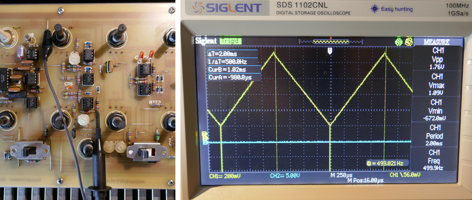
| Triangle Symmetry | ||
| Preset Adjustment | RV15 | |
| VCO Shape | RV14 | CW |
| Place Scope probe (x10) on junction of R57 & R59 | ||
| Press Top C | ||
| Adjust RV15 until the triangle wave is symmetrical. Use transpose switch to check 2 octaves up and down. | ||
| A small negative going spike at the bottom peak will be seen. | ||
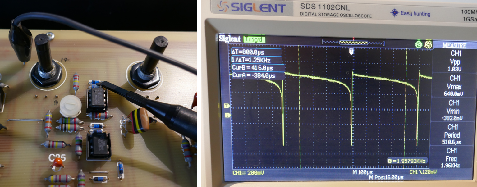
| Square Wave Max PWM Duty Cycle | ||
| Preset Adjustment | RV11 | |
| VCO Transpose | SW5 | RIGHT |
| VCO S-OSC Shape | RV10 | CCW |
| VCO Shape | RV14 | CW |
| Place Scope probe (x10) on junction of D13 & D14 | ||
| Adjust RV11 until nearly 100% duty cycle but with definite negative going spike. | ||
| Test duty cycle range approx 45 to 98% by adjusting RV14 | ||
| VCA Control Breakthrough | ||
| Preset Adjustment | RV22 | |
| S-OSC Speed | RV32 | 3 |
| ENV Attack | RV24 | CCW |
| ENV Sustain Level | RV29 | CCW |
| ENV Decay | RV27 | CCW |
| VCO Level | RV16 | CCW |
| Noise Level | RV33 | CCW |
| ENV Repeat | SW7 | LEFT |
| Scope on High Output | ||
| Momentarily Press Top C | ||
| Adjustment of RV32 may be needed to repeat the breakthrough. | ||
| Alternatively repeat hit Top C to see breakthrough effects when SW7 set MID. | ||
| Adjust RV22 until breakthrough has disappeared or very minimal. | ||
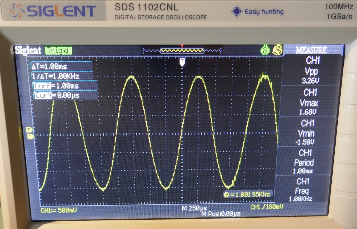
| VCF Pitch Spread | ||
| Preset Adjustment | RV20 | |
| ENV Repeat | SW7 | RIGHT |
| VCF Control | SW16 | LEFT |
| VCF S-OSC Sweep | RV18 | CCW |
| VCO Level | RV16 | CCW |
| VCF Resonance | RV19 | CW |
| Scope on High Output | ||
| Press Top C | ||
| Oscillation is shown on output | ||
| Adjust RV19 until 1KHz is generated | ||
| Press key two octaves down and should show 250Hz | ||
| Adjust RV20 until 250Hz is generated | ||
| Check that one octave down is 500Hz | ||
| ADSR Alignment (Release Gating) | ||
| Preset Adjustment | RV28 | |
| VCF Resonance | RV19 | CCW |
| VCF Frequency | RV17 | CW |
| VCO Waveform | SW4 | CCW |
| VCO Shape | RV14 | CCW |
| ENV Attack | RV24 | CCW |
| ENV Sustain Level | RV29 | CW |
| ENV Decay | RV27 | CCW |
| ENV Release | RV25 | CW |
| ENV Repeat | SW7 | MID |
| ENV Bypass | SW9 | RIGHT |
| Audible method: Press key and listen for release ending gracefully. Adjust RV28 if cuts off early or late. | ||
| Scope method: | ||
| Attach scope channel 1 to D30 Cathode, scope channel 2 to junction R102 & R105 | ||
| Check that channel 1 shows the envelope ending gracefully at the switching point shown on channel 2 | ||
| Adjust RV28 to prevent abrupt or late ending of the envelope. | ||
Resources
ETI Magazine
A copy of the ETI magazine articles can be found by clicking on the image below:

Click to access Transcendent%202000%20Synthesizer.pdf
YouTube
A fabulous series of YouTube videos by Telefunkian
Copyright © 2023 Super Synth Projects, Guy Wilkinson. Telefunkian, midierror

You must be logged in to post a comment.