Yamaha DX5 is a fabulous instrument consisting of two DX7 sound engines to increase the number of voices as well as provide interesting options for dual and split modes.
Jim Daneker and Allen Coppock approached me for an OLED display that would work in Jim’s fabulous DX5. Allen was in middle of an extensive restoration to not only bring the instrument back to life and improve audio quality, but address many cosmetic issues including crafting new side cheeks.
The overall result of Allen’s work on the restoration is simply stunning. The DX5 will surely enhance Jim’s sound palette in his daily working life.

Jim Daneker
Composer, producer and arranger working across a vast range of styles and fields.
Synth Spa – Allen Coppock
Modifications and repairs to instruments with rarely found attention to detail. Allen has high demand and it is clear why this is so. The expertise and craftsmanship are second to none.
Many thanks to Allen and Jim for their effort and dedication to making this happen for the fabulous DX5.
Replacement Display Trials
After trying various options, we decided to trial the OLED used in the JX10 / MKS70 OLED kits as a Winstar WEH4002 display was not easily available and proved to have some minor display issues.
We got a result that is not only stunning, but relatively straightforward to fit. Fitting a new LCD is an issue in this instrument due to very little clearance between front panel and panel board (modern LCD with LED backlights are very deep and not in keeping with the elegance of a DX5). The OLED we used meets the dimensional spec of the original.
Display Characteristics
There is a characteristic of this display whilst editing parameters with the slider. We are not sure how this may be caused, but one explanation could be that OLED has a rapid response time compared with LCD and the way that the DX5 software writes values to the display could be visible when using OLED. For examples, new characters changes overlaying in between scans and repositioning of cursor in between write operations.
A video that a customer sent us of this characteristic, is available at this link: DX5 OLED Update Characteristics
The video also demonstrates how rapid the response time is of the OLED, as well as high contrast and vibrancy.
OLED Availability
If you want one of these displays and up to the job of fitting it, I am happy to supply one. See my availability page for details. It is normally supplied as part of the JX10 or JX8P kits and was specially made to order. It has a very thin construction, small dimensions and a US2011 controller. The SuperJX applications were very tricky due to space requirements, so needed these characteristics. See this guide to using our standard 40×2 OLED module.
Looking at forums around the web, I noted that OLED displays available from well known distributors almost work with the DX5 but have shifted characters in Single Mode. Winstar WEH4002, also branded Midas, Raystar, Vishay, does not quite work properly but does fit correctly as per this guide.
If anyone has used a Winstar OLED, we would love to understand if the same characteristics are shown when editing parameters.
Remove LCD Display
First remove the old LCD display. The Electro-Luminescent back light strip can easily come out on end of it’s cable. Just unplug the connector with the red wires, this is not used with the new display.

OLED Wiring
Disconnect the LCD display from the Panel Board and remove the wires, one at a time and solder to new OLED. This must be performed on an ESD safe bench otherwise damage could occur causing lost characters or complete failure.
It is a good idea to take a photo of the wires to identify the colours if they are different to that in this guide for checking later.
The OLED has two extra pins, 15 and 16, they are legacy options where the OLED is replacing a display with a modern LED backlit LCD.
Once complete the wiring should look like the picture below.

Initial Testing
It is a good idea to test the OLED before it is mounted in the brackets. Using something insulate underneath the Panel Board, in this case plastic packing foam, check all wiring and switch on. The display should power up as shown in picture below.

Mounting
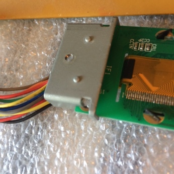
After testing, fit the display to the metal brackets on the Panel Board. The left hand side is retained and the right hand end uses the two original machine screws.
When fitting the display, there is a little play from left to right due to tolerance differences. It is necessary to push the display as far left as possible before tightening the screws, otherwise the wires could show through the window. It also ensures that the right hand bracket does not touch any traces on the OLED display board.
It may be necessary to loosen the brackets from the Panel board to slightly move the display to the left.

Once brackets are fitted and in place, retest and confirm that menus work properly in both single and dual modes.

Backlight Power
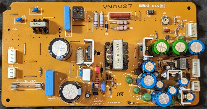
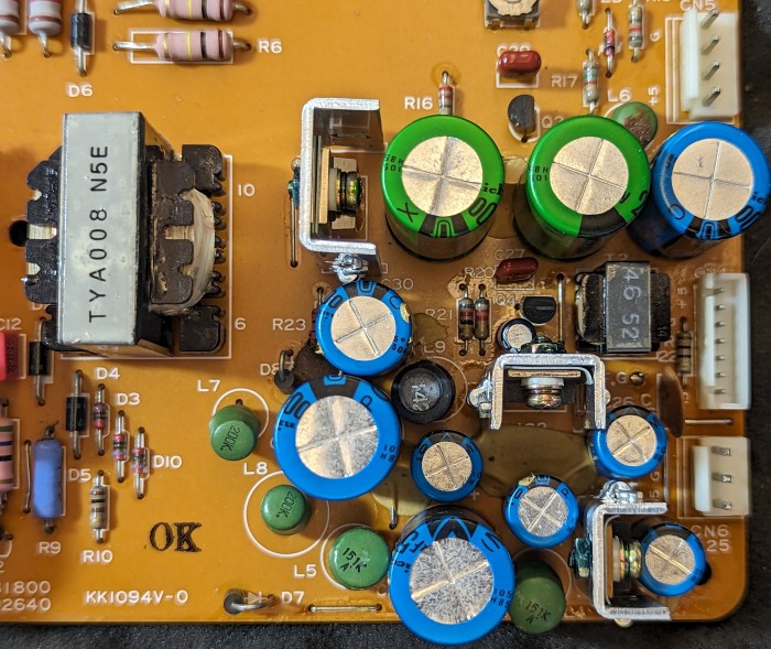
One customer disconnected the transformer or circuit that generates the HT for the EL film on the old display. They claimed that it improved the noise floor slightly.
We don’t know what to recommend because we don’t have access to a DX5 schematic. A similar thing was done on the MKS 80 upgrade, under “Inverter Disconnection”. Usually this circuit is located on the power supply and has a feed inductor that can be easily removed.
If you have any pictures and would like to share, we’d love to feature them.
The Yamaha DX5 Power Supply Board is shown below.


Some techs are reporting that they often replace the power supply with a Meanwell RT-65C which does not have a backlight power output and is therefore ideal when using OLED.
Additional Information
A few extra pictures showing the metal bracket and how it interacts with the display module. The left bracket near the wiring is completely clear and the right bracket could potentially touch a disconnected chassis ground pad if the module is fitted hard right. Fitting hard right would expose wires through the window plus ground is safe to touch in this case..
DX5 Looks Stunning

Copyright © 2020 Super Synth Projects, Guy Wilkinson, Jim Daneker & Allen Coppock


You must be logged in to post a comment.