
I have been lucky enough to have owned a Cyrus system for a long time. It consisted of a Stream XP, CD player, X Power amplifier and Power Supply. A CD8X is pure overkill in my set up because it’s only used as a transport. The Stream XP has no analogue inputs. This means that Cyrus elements aside, we essentially have a junk Philips mechanism/servo PCB from a ghetto blaster, feeding a glorious Stream XP via SPDIF.
In recent years the CD8X Player acted up, first refusing to play CD-Rs that I had created on my Pioneer CD recorder, before finally refusing to play any disc.
In 2022, I had quite an adventure with the CD8X and it is documented in this article with the hope it helps others and prevents units being scrapped.
The whole experience has led me to conclude: What was a great CD player, could have been stellar quality.
Needless to say, the design aspects of the Cyrus elements are great but there was an oversight with the Philips mechanism & servo board interface.
CD Playing Up
Initially, I checked all power supply voltages. The servo board is very fussy on supply voltage and it is poorly regulated by the Cyrus board, although it has an astonishing amount of bulk capacitance too. Trimming the voltage to the Philips spec made no difference. Also repaired a manufacturing fault where a wire fell out of a poorly crimped Molex connector to the servo PCB. Imagine my joy, “this is it!”…. only to find it performs a more consistent failure mode.
Next, my instinct was to swap the VAM1202 mechanism with a replacement CDM12.01, I thought it was strange because it didn’t get many hours of use.
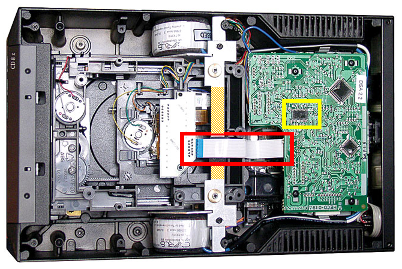
However, once the VAM1202 was replaced, the player still performed in exactly the same way: Once the back was off and the player turned on it’s side, it read the TOC with extreme difficulty before playing CDs perfectly. If my hand was placed near the cable or IC903 highlighted in the picture, sound would become distorted or drop out of play. First reaction was to stupidly buy a new IC from eBay. It was a tricky task to replace, as it was fixed to the PCB with epoxy glue……. made no difference.
Research
Looking around forums in 2022, there was little information. Most people had replaced the mechanism and it worked again or not at all. However, there were similar issues on other high end players using the Philips HECD-019A servo board. I knew nothing about CD Players, but after some research I realised that the signals passing from the head were radio frequency. I also noticed that the cable on the CDM12.01 was actually 10mm longer. Looking at the design, Cyrus engineers had extended the cable so that the servo board could be packaged in their standard enclosure. Normally in a design, the VAM1202 / CDM12.01 would plug direct into the HECD-019A servo board. This pointed towards improper matching or attenuation of signal, so shielding could help get it back from borderline working.
Modification
Three elements were introduced:
- Screen IC903
- Shield the cable
- Remove a section of the support bar
During first test with lid off, the player came into life, reading the TOC with ease and playing without issue, however, putting the lid back on without every screw in place caused issues again. The lid has conductive paint on it and relies on the 4 screws to ground it to the casing. Once this is in place the player functions, but makes me a little suspicious. I think more shielding, with respect to the ground points on servo board, is needed.
In my opinion, the Philips servo board is crying out to be a 4 layer design with proper grounding arrangement. In later designs using newer Philips arrangements, like the CD8SE, have the amplifier chip, IC903, integrated onto the read head this driving a strong signal down the cable to the decoder.
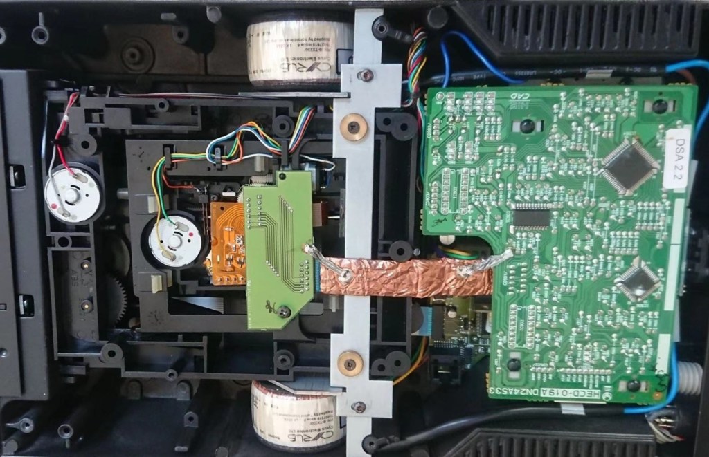
An overview picture of the modifications is shown below. If the support bar is not sectioned, it is vital that it does not electrically come into contact with the new shield. It is recommended that the shielded cable is also held away from the casing. Allowing different grounds to touch will result in loops forming that allow noise to propagate around the circuit. This is especially true if using the analogue outputs.

Adhesive copper tape was used for the cable and copper sheet was used for covering IC903.
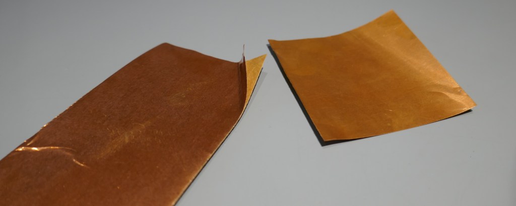
A cable shield was first made with the adhesive tape, most of the backing is left in place to act as an insulator. A 1mm thick ruler was used to form the tape into a rectangular tube, then without cable fitted, stitch with a few blobs of solder along the seam. The tape was overlapped by 5 to 10mm, of which a few mm have the backing removed. Four pieces of braid were attached, ready for the ground points on the PCBs. Four pieces were employed to ensure very low impedance to the PCBs.

The picture below shows how the arrangement was put together, some insulation was used in places to ensure no short circuits could occur. On the extension PCB, solder resist was removed to attach the shield connections. On the servo PCB, two ground points were chosen, one close to the IC and other on the connector. These leads must be kept as short as possible otherwise the shield will be rendered useless.

The copper sheet was cut with scissors to make a flat shield on top of the IC, with a ground connection point to the trace that runs under the IC. Solder resist was removed, fluxed, tinned on the trace before the shield was attached. It is vital that the shield is cut carefully so that it does not touch any other trace or connection.
The inside of the lid is plastic and non conductive, so there is little danger of anything touching the other ground elements.

The power circuit has no protection, any short circuit of the power rails will result in much of the PCBs turning into toast, especially considering the amount of capacitance that’s employed in the design.
That concludes my modification, but note that it won’t work when the lid is placed in situ without all 4 screws in place. Ideally, if we were designing this enclosure from scratch, the lid should have at least 10 screws to effect a good ground connection, but this is impossible with this enclosure design. Drilling into the enclosure is not advised as it is likely made of magnesium alloy, that can burst into flames when worked.
Later Research on Forums
Later in 2023 when I was writing this article, I decided to look up the CD8X again and see if anyone had come up with interesting fixes. After all, it is a flagship CD player that cost a lot of money in 2004 and was regarded as state of the art. There are regularly players for sale on eBay that are sold as faulty because they can’t read a disc.
Clone of Philips Servo Board
Here is a picture of a HECD-019A clone made by cac liu on diyauido.com in early 2023
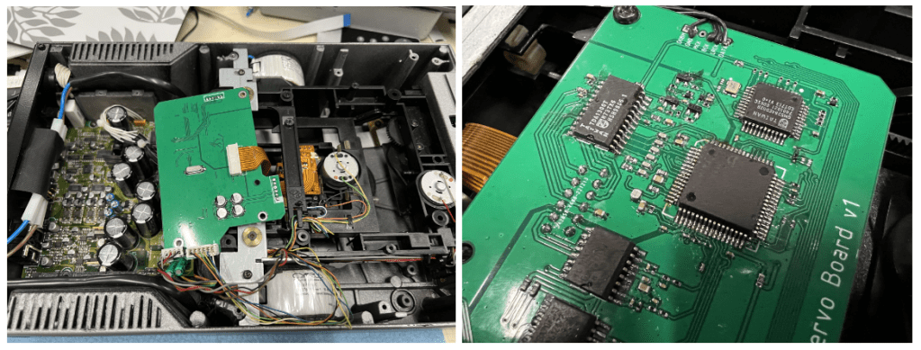
It is very interesting because the clone was designed specifically for the CD8X, addresses all the issues and connects directly to the VAM1202. The PCB mounts over the top of the mechanism where it should be, nicely away from the DAC and power supply. A different micro-controller was used and code was written to emulate the old Philips part. Meaning that no modification to the Cyrus board is needed. It is something that Cyrus did in later models of CD players. The forum is interesting because others have attempted to make a clone PCB too, but kind of stalled at the reverse engineering of the firmware. They don’t seem interested in cac liu’s project, but it is a great piece of engineering and something I would love to build, if cac liu made the firmware available.
Shielding Fix
The idea of shielding the cable it seems is not new. An earlier post on diyaudio.com by cac liu was made late 2022 with a suggestion to another member that shielding just the cable will fix the CD player. It was made by the same guy who later came up with a clone servo board for the fun of it.
Parts
I got a CDM12.01 (equivalent to VAM1202) that fitted in my CD8X and can be purchased from Cricklewood Electronics – Link
It seems that CDM and VAM parts are not the same if you read this article. I would love to understand what tweaks they made to the design, they look almost identical side by side.
The Boring Stuff
Soldering Skills
Just adding shielding without grounding it, will not work and make the issue worse. This modification requires good soldering skills but is actually pretty straightforward.
ESD Management
The VAM1202/CDM12.01 read head is extremely sensitive to static electricity damage, causing it to not work or stress it to partial working. Whilst working on this player it is really important to do modifications on an antistatic work mat, wear an ESD wrist strap and use an ESD safe soldering iron.
Power
Note that the unit when in standby, it is actually fully powered and all circuits are on. If a short on a supply occurs, then with the huge amounts of bulk capacitance used in the power supply, impressive damage can occur in a flash.
Whilst testing the unit during tweaking and testing with the lid off and plugged in, be wary of touching the mains input connections. The UK & EU have a pretty dangerous 230 V AC and it isn’t fun to add to the personal “shock counter”. In my case I have had 11 shocks in my life, with each one feeling worse each time.
Copyright © 2023 Super Synth Projects, Guy Wilkinson

You must be logged in to post a comment.