Copyright © 2024 Super Synth Projects, Guy Wilkinson
A fabulous Oberheim OB-X getting a huge overhaul, involving replacement of many integrated circuits and tantalum capacitors, the processor board needed attention. Memory ICs had failed, swapping the P2111A devices with others from a parts box brought it to life, but storing patch data was not possible.
This article shows a solution for replacing the HM6508 and P2111A devices. If your OB-X has an Encore MIDI interface, then this fix is not needed, however if you have a Kenton interface or keeping it original, then this is a nice solution.
We can supply blank PCBs if you would like to perform this modification.
Memory Components
Picture below shows the memory components on the Rev 1 & some Rev 2 memory boards, 1K x 1bit memory is CMOS and ultra low power so that it can be powered by an internal battery.
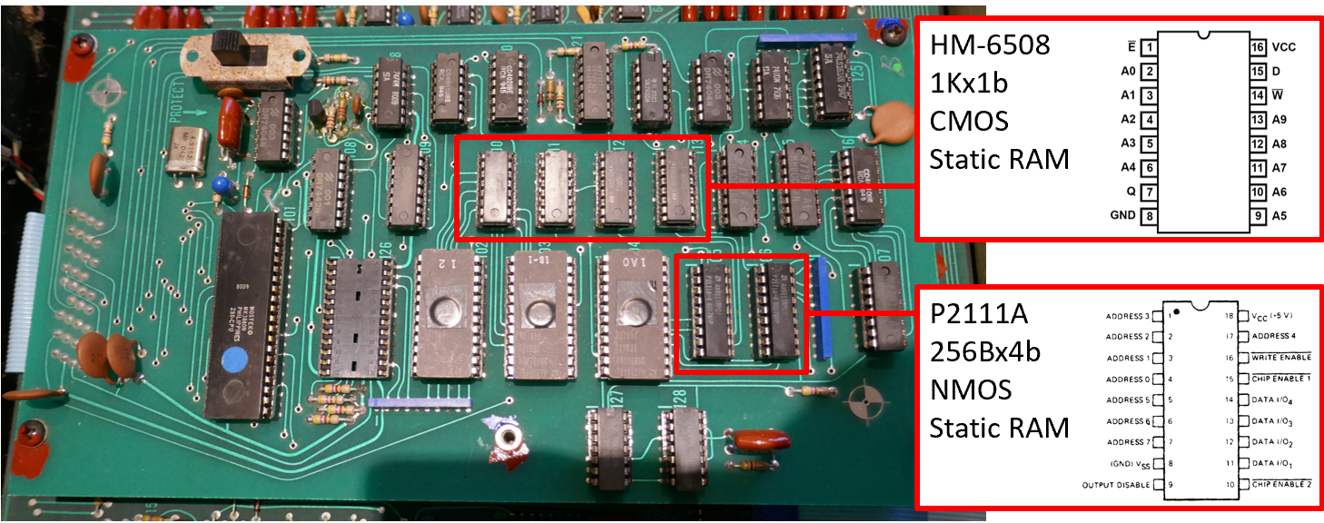
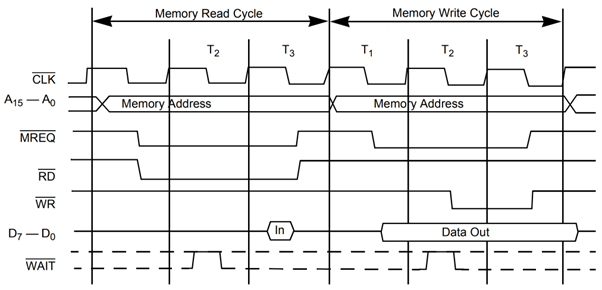
It is a simple task to replace these ICs with modern components and the Z80 timing arrangement is shown below to confirm that everything will go together in respect of timing and bus contention.
Patch Memory
A circuit diagram of the Patch Memory using 1 bit memory chips is shown below.

At first glance there is no use of /RD for enabling the data output, it is instead driven by chip select and the /WR signal. Looking at the Z80 bus timing arrangements there is an issue with contention. During write on a Z80 bus, the RAM output is active 100ns after MREQ and data bus is active for 406nS before nWR is activated.
The design does not use /RD and in fact due to the slow access time of the HM6508, there is only a short time that bus contention is present. The engineers must have worked around the limitations of memory in it’s day to save on logic devices. The HM6508 is quite an odd ball by modern standards having separate data in and data out pins, it was the only available device that could be powered by a battery in the 1970s. Using a replacement modern device requires a /RD signal to be brought to it.
A PCB was designed to hold a replacement memory chip to hold patch data. A switch was added too, so that I could store factory settings as well as a bank for testing, calibration and general messing about.

Two options for memory ICs are possible:
Volatile CMOS S-RAM – ISSI65C256AL
Battery is required in the power supply to power the device when the system is off just like the existing scheme. Unlimited writes to memory, ok for any application.
Non-Volatile F-RAM – FM1808B-SG
Battery needs to be removed from the power supply and a diode replaced with a wire link to power the memory from +5V instead of +5VMEM. Limited writes to memory, perfectly ok for patch data.
Components used
- FM1808B-SG or ISSI65C256AL
- 10K 0805 SMD Resistor
- 220n 0805 SMD ceramic capacitor
- Turned pin header strip Harwin D01-9922046
- SMD Switch if bank selection is wanted Alps SSSS810701
Main Memory
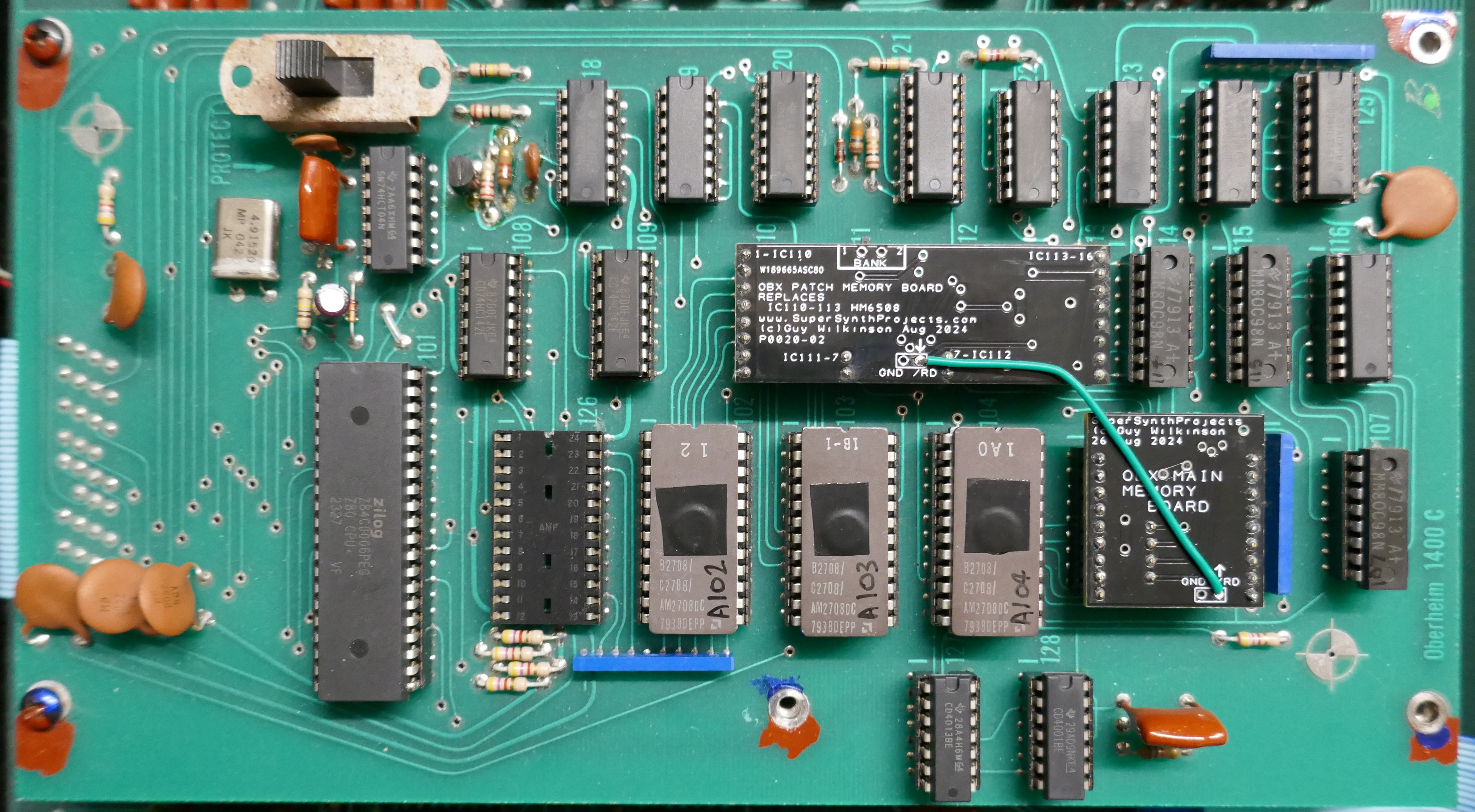
The main memory circuit for running the program and storing temporary data is shown below and is arranged into 256 x 8 bits. It has pretty conventional arrangement for interfacing to the Z80 with /RD & /WR.

A PCB was designed to hold a replacement memory chip to hold working data that simply plugs directly into the two sockets for the old chips. It also provides a break out of the /RD signal so that a wire can be attached between the patch & main memory PCBs. F-RAM could be used in this application however it has limited number of writes and would probably fail after a few years, so normal static RAM ISSI65C256AL was chosen.

Components used
- ISSI65C256AL
- 220n 0805 ceramic capacitor
- Turned pin header strip
Final Solution
The final solution is shown below, the patch memory board having FF-RAM fitted instead of SRAM. Both options were tested.
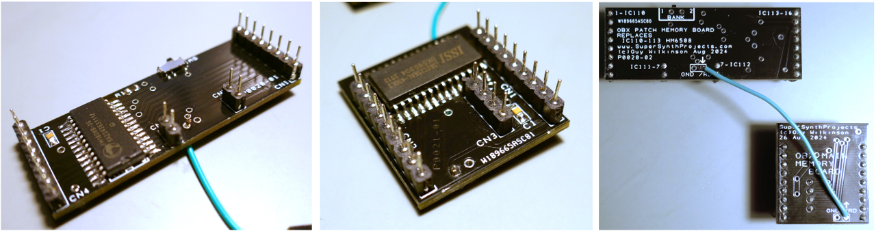
A picture of the two installed PCBs is shown below and the interconnecting /RD wire.

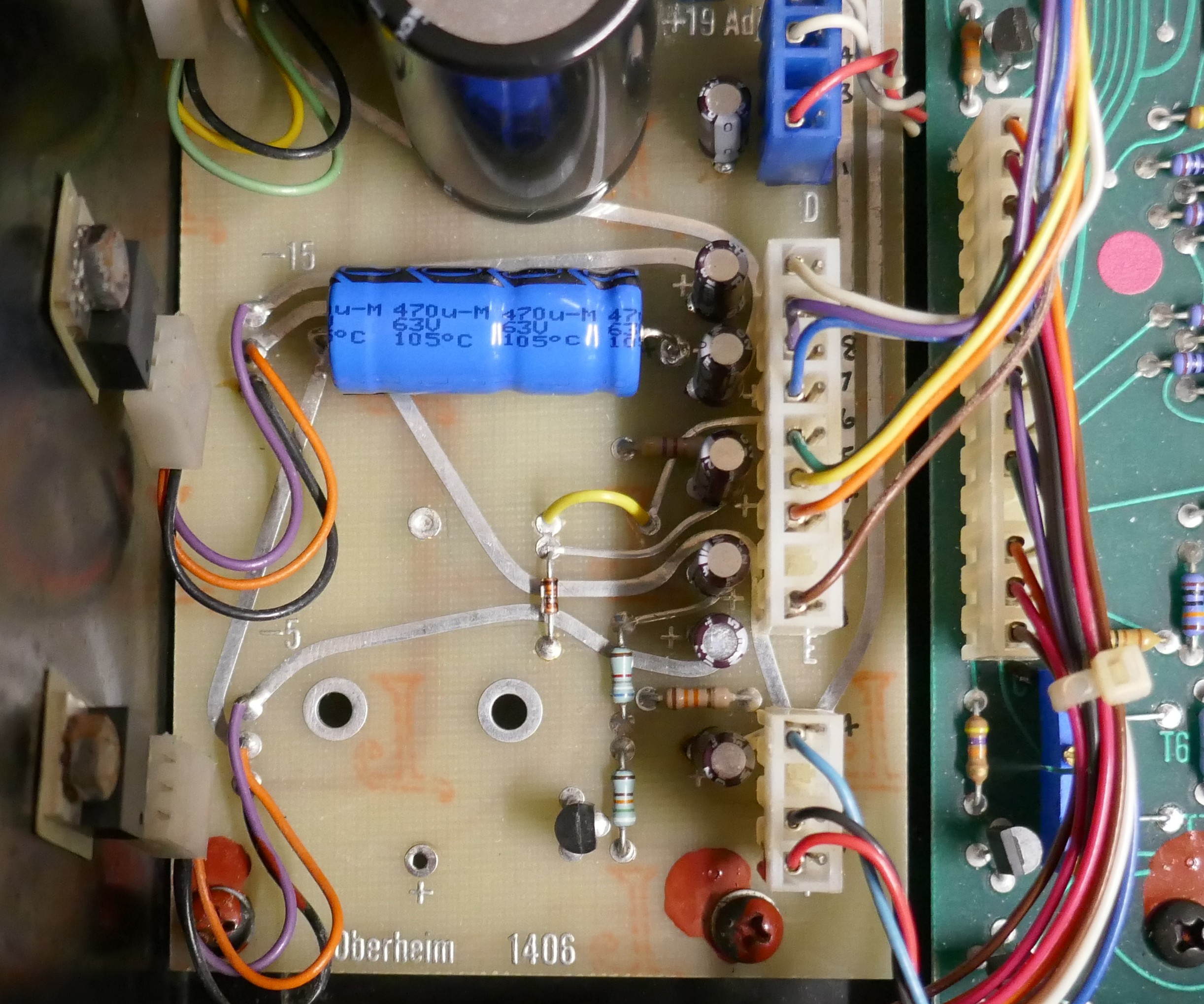
Power Supply Modification
In this application, the F-RAM for the patch memory board was chosen so that the battery could be removed completely. This allows disconnection of the PCBs without losing any data. The diode that connects +5V to +5VMEM is replaced with a wire link that is yellow in the picture below.

You must be logged in to post a comment.