I had the opportunity to study the JX-8P chorus circuit, perform listening tests and make some simple adjustments to improve the noise arriving out of it. These improvements are worthwhile if you were changing capacitors as part of an upgrade or service, the changes improve the noise floor of the JX-8P, now that modern capacitors are smaller in physical size.
Background
The JX-8P has an interesting chorus circuit that at the time was designed for cost when at the time op-amps were expensive. I have seen many posts online where the SuperJX (JX-10/MKS70) is regarded as inferior to the tone of the JX-8P circuit.
Frankly, I disagree. The SuperJX circuit is more accurate than the JX-8P and squeezes out a fraction more bandwidth, it is also noticeably lower noise per tone board. All due to the op-amps used in the design, better response and higher supply noise rejection.
The JX-8P adds colour to the sound due to its poorer linearity compared with SuperJX; exactly what you would expect for an uncompensated transistorised circuit.
The SuperJX has a disadvantage that many sounds use both tone boards for layered sounds so any chorus noise is multiplied by 2. However, the JX-8P is seriously disadvantaged by a design flaw that couples noise or hiss into the chorus circuit from the supply rails.
Circuit Issues
The diagram below shows the primary path of how noise from the power rails reaches the circuit and ends up being amplified by the limiter. This is the primary source of noise, a little as 5 mV will get added into the signal path and amplified slightly.
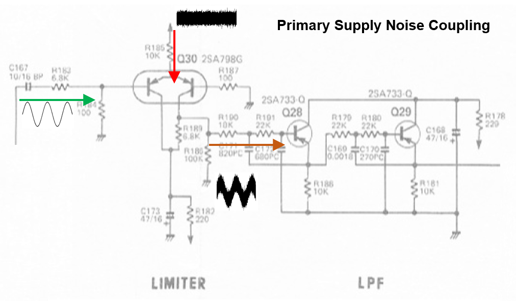
All that is needed is some additional decoupling for the +15V reference supply.
Circuit Modifications
Looking around the circuit, supply decoupling is placed in key positions. The diagram shows these areas, plus the modification to remove the primary source.
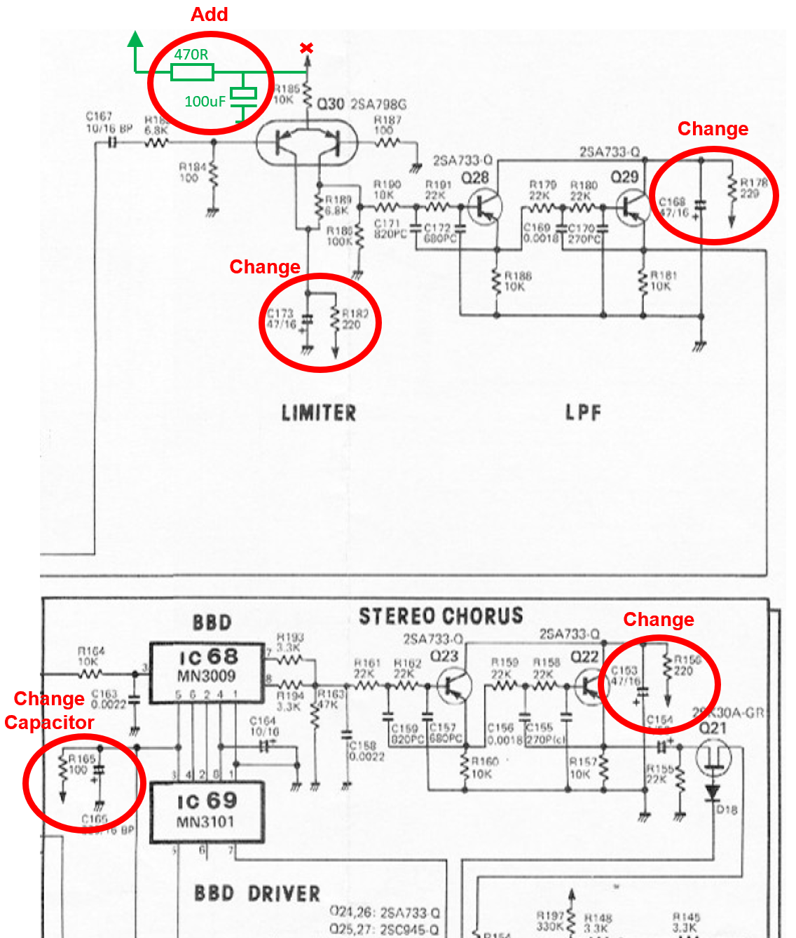
These are all values that are easily changed and provide a big win in terms of performance. A summary of changes for both circuits, noting that there are two sets of duplicate circuits is:
- C165 (x2) change to 470uF >15V
- R182, R178, R156 (x2) change to 470 ohms
- C173, C168, C153 (x2) 100uF >15V
- R178 to 470R
- R185 in series with 470 ohms, the node of which goes to a capacitor 100uF >15V + and it’s – to TPAG, use a bit of sleeve to prevent short circuits.
The modifications do make a positive impact, if anything it makes the usual chorus “whooshing” more obvious, because it now dominates the overall noise heard.
The keen eyed will also notice that the VCA circuit is impacted too, there is a lack of decoupling on Q20 resistors, R153, R151 & R197. There are two sets of these circuits for each left & right outputs, so it would be a significant mod on the VCA to do this. Looking at the PCB layout the modification would be too much. The reason why supply noise does not impact the VCA too much is the differential action of IC67 cancelling it out, however it does still get through a little.
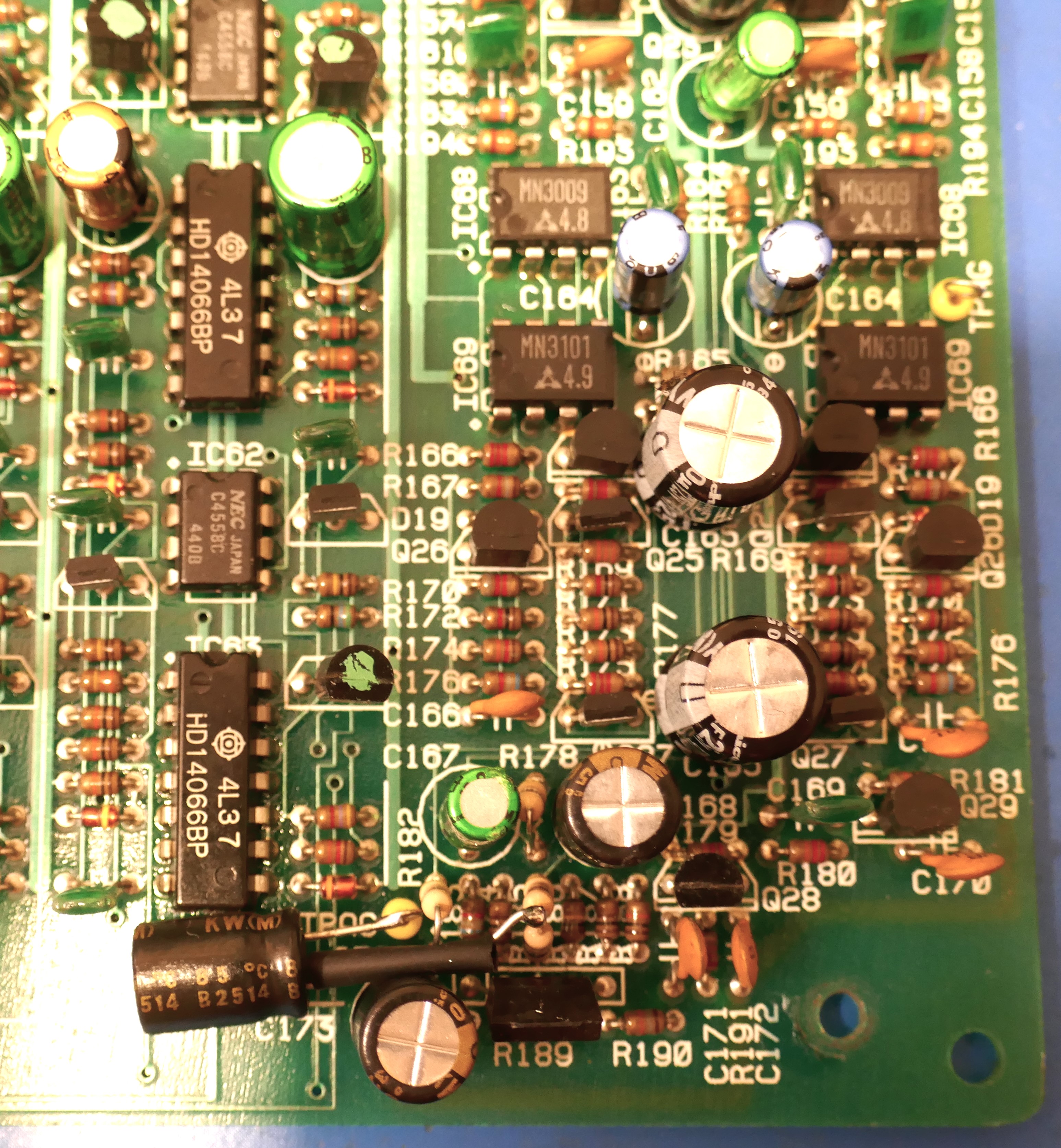
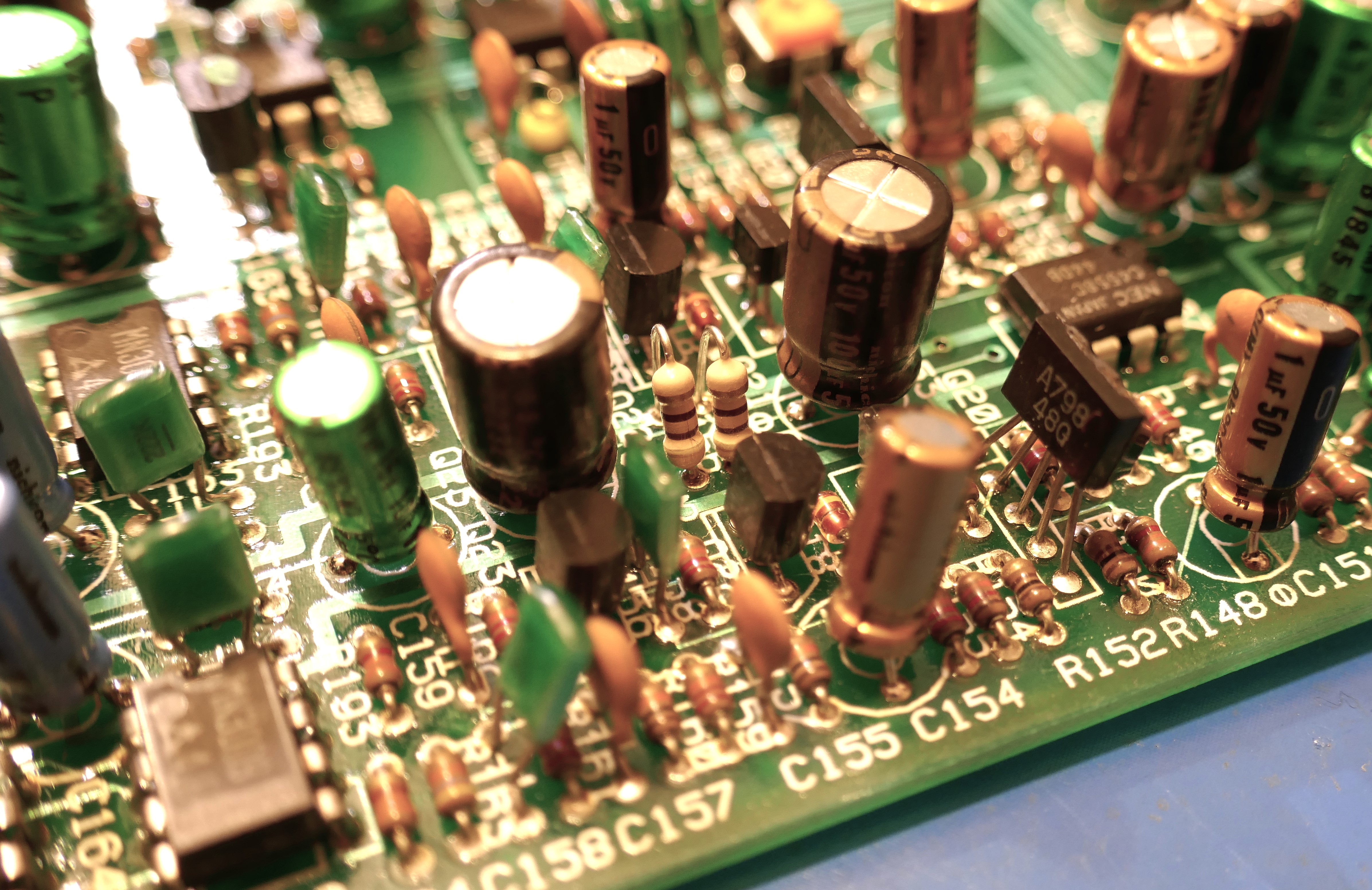
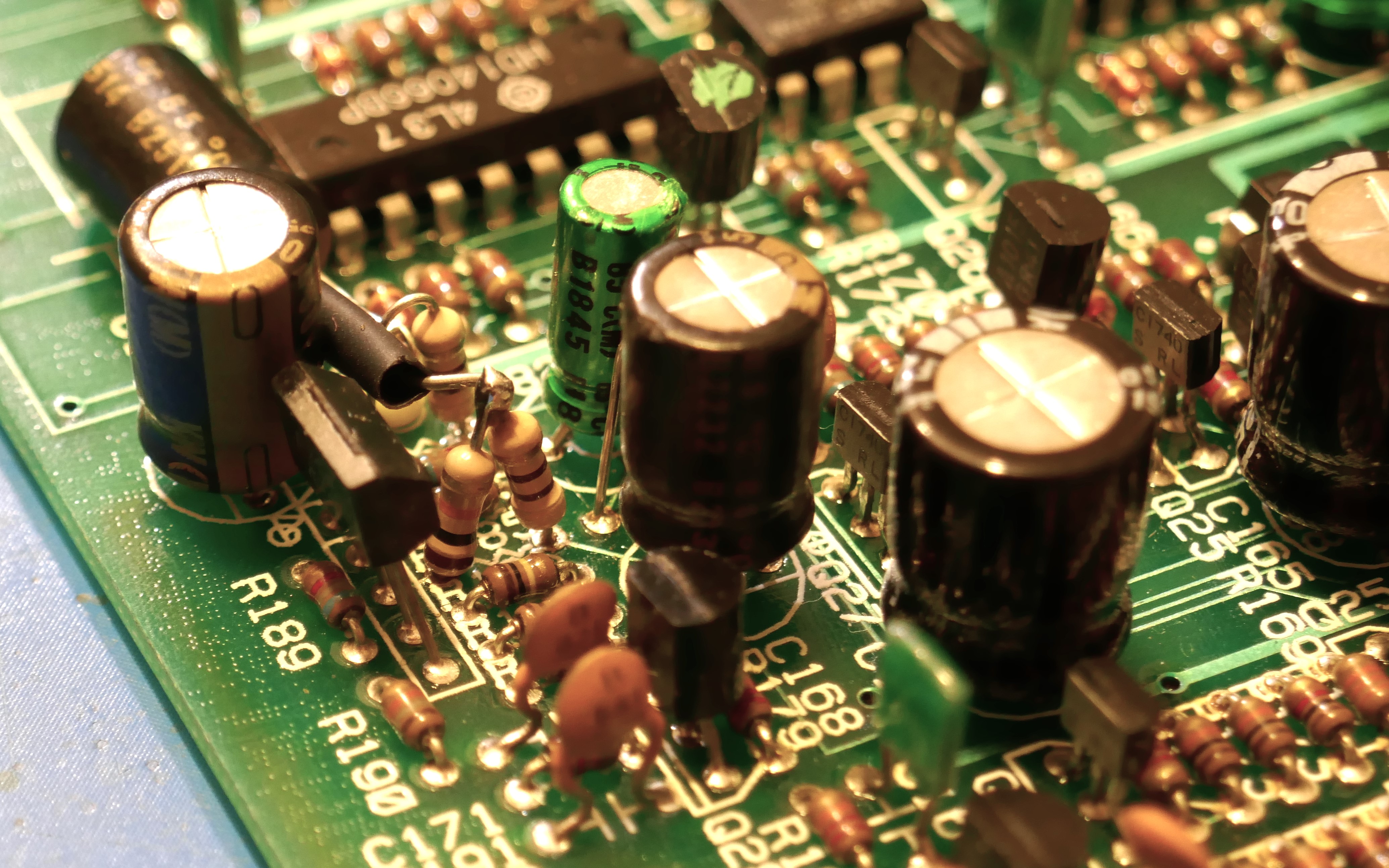
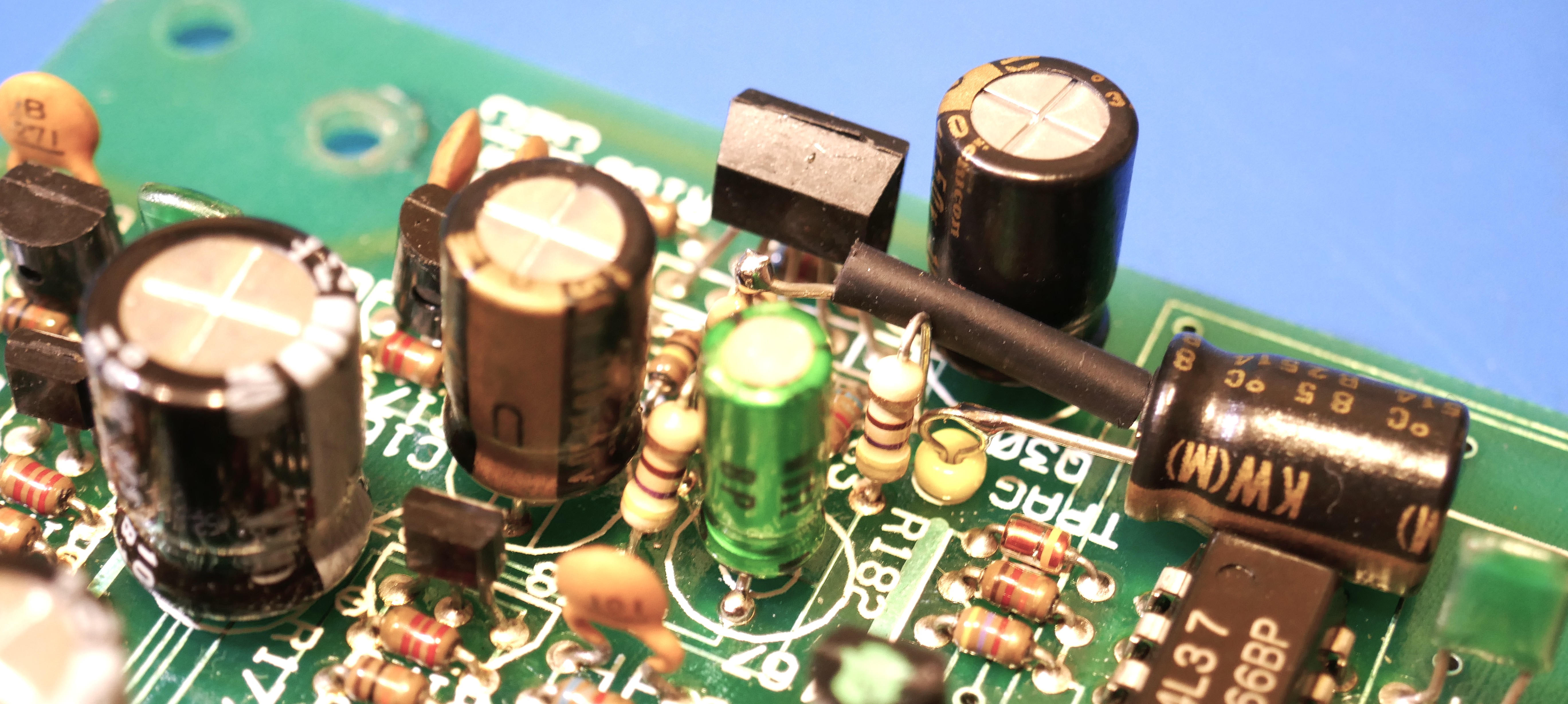
Some pictures of the final mods are shown below.

You must be logged in to post a comment.