This page details step by step how to replace vulnerable components in the SuperJX Power Supply for JX10 or MKS70. It is a very long guide but covers all techniques to ensure a reliable board and a quality piece of work.
All techniques can be applied to other Linear Power supply boards in other instruments, for example, the Roland JX8P with exception that the transistors are mounted with mica insulators.
See the Power Supply Information page for parts lists and where to obtain them from.
If you want to know how to remove the power supply board, the JX10 is easy, but details for the MKS70 is on this page: MKS70 Board Removal
Tools
Here is a quick summary of tools you need to do everything:
- Temperature controlled iron
- Desoldering tool
- Unblocking tool for above (large unwound paperclip)
- Pointed tweezers
- fibreglass pen
- Screwdriver suitable for roland gear
- small flat blade screwdriver
- Wire cutters
- Pliers
- Toothbrush
- Anti-static mat & wrist strap

When working on SuperJX PCBs, it is always a good idea to use anti-static mat and wrist strap to prevent weakening of semiconductors. It has been known to not only damage but alter the performance of ICs.
Consumables
- Solder
- Soldering braid
- Superglue
- IPA
- Cotton buds / q-tips
- Tissue
- Heatsink compound
- Silicone sealant
Capacitor Removal
If replacing capacitors it is best to remove them first before undertaking repairs because they get in the way.
First remove the solder off the capacitor terminals. Desoldering pumps have to be “poked”, dismantled and cleaned regularly and can be difficult to use when removing a large amount of solder. The best way to avoid frustration with cheap hand pumps, is to remove a small portion of the solder on the capacitor terminals at a time and remove solder that has stuck in the nozzle by poking a metal rod up it.

After removing most of the solder, pull them out, it may be necessary to heat a joint if some solder remains. Note also that you will be pulling against the glue.

Remove the remaining glue and clean the area of the board.

Tag Terminal Clean Up
Now that the big capacitors are out of the way the tag terminals will need to be cleaned up because they will have excess solder and remains of wire looped through. Note that you don’t have to remove the excess wire loops, they can stay there. Depends if you are electronic OCD 🙂
MKS70 Step: Suppression Capacitors
There are additional noise suppression capacitors (ceramic disc 4n7 100V) that need removing first otherwise they can be damaged by excessive heat when removing solder and wire loops from the tags.
Using tweezers, remove the capacitors by heating the joint and lifting them out. Try not to apply any force and get them out as quickly as possible. Do not damage the insulating sleeve otherwise when replaced the AC power will be short circuited. Check for damage of insulation once removed.
Remove Excess Solder
Remove excess solder from each tag using a desoldering tool.

Removing Wire Loops
If removing the wire loops, use stainless steel pointed tweezers to poke through the loop whilst it is heated and pull it away leaving a clear tag.
MKS70 Step: Fit Suppression Capacitors
Remove the solder inside the tag mounting hole. This will allow the suppression capacitors to be fitted easily with minimal heating.
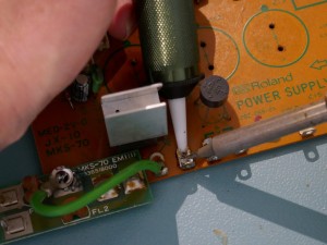
Replace the suppression capacitors by melting the solder in each of the other tag mounting holes and poking the capacitor leg through the molten solder. For the capacitor that straddles across the two outer terminals, ensure that the insulation is clear of the tag so that it doesn’t melt when the tag is heated later. Once done turn over the PCB so that the last hole can be soldered. Take care not to apply heat for too long.
Check
The suppression capacitor legs can easily short together and permanently damage the transformer when fitted. Inspect carefully for adjacent leg short circuits and use a continuity tester to check that there are no shorts between each of the terminals. A minute amount of glue can be used to hold the insulation as close as possible to the body of the front capacitor.
Now we have clean tags that are wire free ready for later re-installation of the board.

Transistor Replacement
The transistors required are shown in the table below:
| Ident | Replacement Part Number |
Quantity | Type |
| Q5 | 2SB1015 | 1 | Power, PNP |
| Q1, Q4 | 2SD1406 | 2 | Power, NPN |
| Q3 | 2SC1583 | 1 | Matched Pair |
| Q6 | 2SB605 | 1 | Signal |
Remove screws holding the transistor tabs to the heat-sink.

Remove solder from the transistors that you are replacing, in this case, all of them.

Remove excess solder from the power transistor pads using braid. This is essential for two reasons:
- When transistor is fitted, solder sitting across hole causes pad to lift off.
- Lumps of solder get in way when removing the solder resist with fibreglass pen.
It may be necessary to kick-off the wicking process in the braid by putting a dab of solder on it first before running over the pad with braid and iron to achieve a smooth finish.
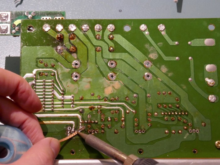
Clean the area with IPA and cotton bud / q-tip to remove excess flux and allow inspection of the pads.

Using a fibreglass pen, remove solder resist on the PCB in locations shown a few pictures later so that a folded transistor leg covers the area to make a larger joint. To make this easier for some pads, the neighboring resistor pad has had solder removed so that the pen can be moved closer to the resistor pad.

When complete, dab an IPA soaked tissue over the area to pick up dust and strands of fiberglass left behind. Take care to remove strands of fibreglass.

The picture below shows what you should end up with. In this case the PCB mounted transistor Q2 has been done as well although this is not necessary unless the pads have been damaged by previous rework.
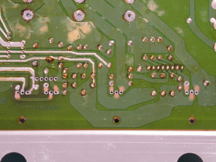
Using solder, “tin” the exposed copper with solder before removing it with a desolder tool. It may be necessary to repeat the cleaning with the fibreglass pen if not enough area “takes” to the solder. Using flux can help here too to get the solder to stick more easily.
The picture below shows what you should end up with: tinned, flat and clean areas to solder the transistor legs onto.

Turn the board over and clean off the heatsink grease and use an IPA soaked bud to remove residue around the transistor legs.
The transistor legs are bent as shown in the pictures below, 3mm from the body at a right angle. The right angle will also allow some slight movement that occurs in the MKS70 when transported. Note the use of an anti-static wrist strap when handling semiconductors.
Place a small blob of heatsink compound on the back of each transistor as shown before fitting to the heatsink. Some very important points at this step:
- The transistor legs should “fall” through the holes easily without force, if they don’t then check that the hole isn’t obstructed with solder or residue that could cause damage to the pad.
- The compound is essential to ensure good thermal conductivity, otherwise the transistor will run hot and have a short life.
- The screws are “self tapping”, so it is essential to fit them initially with fingers so that the screw “tracks” the old thread in the hole. Once in place tighten with a screwdriver. If the hole thread is damaged, the screw will work loose later and have dire consequences.
Once the transistors have been fitted, turn over the board and tighten the heatsink mounting screws before placing superglue on the underside screw heads to hold them in place. Otherwise, if they become loose, additional strain is put on the power transistor legs when the instrument is moved. Roland should have used same screws as for the transistors with shake proof washers here.
Install the PCB mounted transistors in orientation shown below:

Solder and trim the legs of transistors Q2 and Q3, in this case, Q2 is getting same “folded leg” treatment as the power transistors.
Soldering the power transistors involves trimming the legs to a suitable length so that when folded they cover the newly exposed pads. For Q5 and Q4 about 1mm is removed and Q1 about 2mm.
The legs are then folded so that they are completely flat, the best tool to use is a flat blade screwdriver. Q1 has one leg bent at an angle to follow the trace.
Picture below shows the final result; Transistors in place with clean reliable joints without excessive solder.

Other Semiconductors
The IC and diodes can also be replaced with types as shown in the table below using exactly the same techniques for the transistors.
| Ident | Replacement Part Number |
Quantity | Type |
| IC1 | M5230L | 1 | Tracking Regulator |
| D1, D2, D3 | UF4003 | 3 | 200V Fast Recovery Diode |
Bridge Rectifiers
The table below shows equivalent part numbers for replacement bridge rectifiers:
| Ident | Replacement Part Number |
Quantity | Type |
| D4 | VS-KBPC601PBF | 1 | 4 Amp 100V Bridge |
| D5 | 2W01G-E4 | 1 | 2 Amp 100V Bridge |
Remove the solder on the terminals of the Bridge rectifiers D4 and D5. When removing it is best to remove enough solder so that the leads become loose then snip them. They are easy to remove in many different ways. Remove traces of solder around the holes and clean the pads of excess flux to avoid damaging the pads when new rectifiers are installed. It is a good idea to remove residue on the top side too.
Replace the small rectifier allowing it to stand proud of the PCB so that it has good air circulation.
Remove the heatsink from the large rectifier and reform exactly as shown in the picture. It will be necessary to use pliers to straighten the base that attaches to the rectifier. Flatness assists in transferring heat out of the component.
Attach the new rectifier with heatsink compound and secure the screw with some superglue. The pictures below show exactly how it should be oriented with the “flat” on the rectifier (+) adjacent to the angled fin. In the pictures a “kink” has been placed in the negative (-) leg using fine nosed pliers to help keep the rectifier in place when soldering and provide additional robustness.
Install the new rectifier in the board, keeping it perfectly vertical. Note that the leads will be RoHS compliant so soldering will be a little more tricky. If this is an issue, use flux or “tin” the legs first. Final picture shows the orientation and the “kink” in the (-) leg. Check that the flat corner of the rectifier is aligned with the flat corner on the PCB silk screen printing for D4.
Capacitor Replacement
Smoothing Capacitors
Two of the smoothing capacitors, C12 & C13, that were chosen for this MKS70 power supply are 5mm taller (45mm high) and have a higher temperature rating for extended life. They were chosen due to availability at the supplier and will fit in the MKS70. C11 is also 105 degree C and will give worthwhile extended life as it is adjacent to the rectifier heatsink.

The requirements for smoothing capacitors are shown in the table below:
| Ident | Value uF |
Quantity | Pin Spacing mm |
Voltage Rating | Body Dia mm |
Body Len mm |
| Min | Max | Max | ||||
| C11 | 6800 | 1 | 10 | 25 | 25 | 40 |
| C12, C13 | 4700 | 2 | 10 | 35 | 22 | 40 |
Fit the smoothing capacitors as shown in the pictures below using a small pea sized blob of silicone sealant. This ensures that capacitors don’t break away if the instrument is transported but can be easily removed if required. The silicone based sealant used in the picture is Fernox LS-X used as a jointing compound in plumbing.
Check that the polarity is correct before soldering, the negative stripe on the capacitor points to the circle on the silk screen ident. Getting this wrong yields interesting results when switched on and is potentially dangerous.
Decoupling Capacitors
The PCB mount capacitors are often replaced at the same time as the smoothing capacitors.
The requirements for electrolytic capacitors used in decoupling are shown in the table below:
| Ident | Value uF |
Quantity | Voltage Rating | Body Dia mm |
| Min | Max | |||
| C1 | 10 | 1 | 16 | 6 |
| C2, C6, C9 | 100 | 3 | 16 | 7 |
| C3, C8 | 4.7 | 2 | 35 | 6 |
| C4 | 1 | 1 | 50 | 6 |
The other capacitor types could be replaced with a modern ceramic or film (100nF >50V X7R) but there is little point as they don’t usually degrade, they can be removed and checked with a multi-meter if it is suspected that they are causing an issue. The table below shows the requirements:
| Ident | Value nF |
Quantity | Voltage Rating | Lead Pitch |
| Min | Max | |||
| C5, C7, C10 | 100 | 3 | 35 | 8 |
Remove and replace each small capacitor one by one ensuring that the polarity is correct, in same way as the large smoothing capacitors.
It is good practice to clean any residue from under the capacitor before refitting to ensure that any leaked electrolyte doesn’t affect circuit performance.
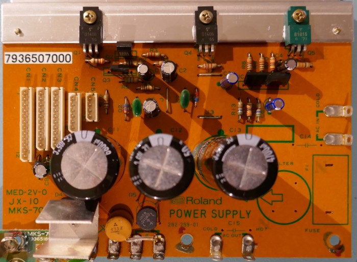
Once all the capacitors have been replaced it should look like this below, double check the orientations of each one, if they are the wrong way round, they have to be removed and refitted.
Resistors
The old design uses mostly carbon film 5%, however the 1% metal film 100ppm types don’t cost much more so can be used throughout.
Basic resistor parameters are:
- Minimum of 250mW power rating
- Maximum body length of 8mm
- Metal Film where possible
Where resistors shown below have a tolerance of 1%, improved accuracy and stability of voltage regulation with temperature can be obtained by replacing those resistors with 0.1% 25ppm resistors such as the TE Connectivity H8 series, for example here.
Resistor requirements are shown in the table below.
Note that R7 is marked incorrectly on the Roland service manual schematic and needs to be 2200 ohms (not 330 as shown). R12 can be same as R9 & R9, they are shown separately for clarity that R8 & R9 have to be 1% Metal Film or better. Note also that on the schematic in the MKS70 service manual, R10 is shown as 240KMF but should be 24KMF as shown in the JX10 service manual (they have identical DC circuits).
| Ident | Value Ohms |
Quantity | Tolerance % |
Drift PPM/C |
| Max | Max | |||
| R1, R11 | 330 | 2 | 5 | 200 |
| R2 | 10 | 1 | 5 | 200 |
| R3, R7 | 2200 | 2 | 5 | 200 |
| R4 | 3600 | 1 | 1 | 100 |
| R5 | 5600 | 1 | 5 | 200 |
| R6 | 1800 | 1 | 1 | 100 |
| R8, R9 | 10000 | 2 | 1 | 100 |
| R10 | 24000 | 1 | 1 | 100 |
| R12 | 10000 | 1 | 5 | 200 |
| R13, R15 | 560 | 2 | 5 | 200 |
| R14 | 3300 | 1 | 1 | 100 |
For identifying the coding on resistors a useful resistor colour code calculator is shown here: Resistor Colour Coding. Beware of 4 and 5 band colour code conventions, the Power Supply Board has a mixture of both types.
Remove and replace each resistor one by one ensuring that they are of the correct value. Ensure that the holes are clear of solder and use braid to remove if necessary. It is good practice to clean any residue from under the resistor before fitting the new one.
Use a multi-meter to confirm resistance before fitting and remove any doubt as to the value. If the PSU was fully installed and a resistor was of incorrect value, overheating or destruction of all boards in the instrument could occur if the transistors were incorrectly biased.
The sequence of pictures shown below illustrate each step for one example resistor R11.
Once replaced, check every resistor again against the table above and the colour coding, getting the resistors correct is critical for reliability.
The picture below shows the section of the PCB where all the resistors are placed. The picture can be used for checking resistors but note that all resistors are 5 band colour coded with tolerance band pointing left or up.

Cleaning Solder Side
If one has “technician OCD”, cleaning the solder side removes excessive flux residue and improves the look of the PCB. This step can be done prior to working on the board to reduce the “smoke” we all love the breathe in when working on PCBs. Ideally this is done using a cleaning bath but most DIY’ers won’t have this kind of facility.
Using a toothbrush soaked in IPA, work on the large dark brown flux deposits until they are diminished. Clean the flux off the toothbrush and repeat until a consistent clean finish is achieved. The PCB will remain tacky as it is impossible nor necessary to remove the flux completely but left over night it will harden again.
Do not allow any IPA or flux residue to reach the connectors on the component side otherwise the contacts will get contaminated.

Completed Board
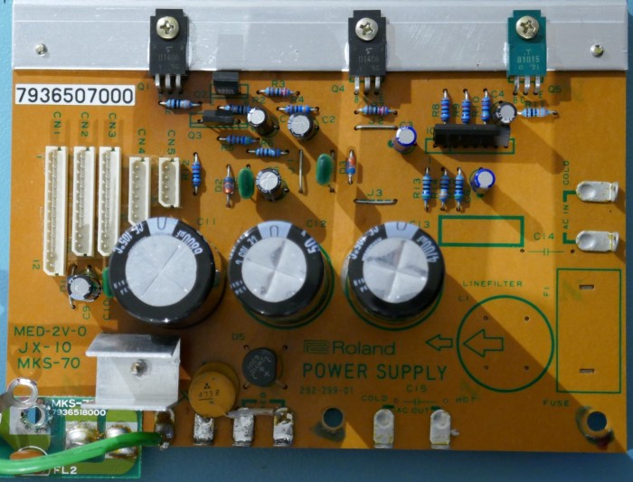
The Power Supply Board should look like the picture below after the key components have been replaced.
Reconnection
Loosely fit the Power Supply Board and reconnect the wires. The preferred method here is to not loop the wire through and over the tag so that it can be removed easily again just by melting the joint.
First the wires are stripped by about 4mm and tinned before being placed through the hole and soldered. Check that the wire end is properly covered in solder. Tinning the wires ensures a reliable joint. It may be necessary to apply flux to the wire as it will be corroded after 30 years.
Note that this MKS has had many years of atmospheric dirt collected on the internals and is due for a clean.
Testing

This step involves working on the instrument with the lid off and mains power on. There is a risk of electric shock at this step, take great care when probing power rails.
Specifications
In this MKS, the 5V power rail was initially 4.80V, but after the resistor change it is 5.03V, an extremely good result with 1% metal film resistors.
For this test, do not connect any of the power connectors that supply the internal boards in case the rails are incorrect.
After applying power and no smoke was emitted, use a multi-meter to check the power rail voltages by carefully probing connector CN4:
- +15V +/-0.6V
- -15V +/-0.6V
- GND
- GND
- +5V +/-0.1V
- +7V Unreg 12 to 14 V unloaded (Nominally 9 – 12V loaded)
The +15V and -15V rails should track each other closely in magnitude to within 0.2V.
Note that a common cause of failure is the regulation circuit inside the IC and tests will show the 15v power rails to be nearly 3v higher than it should be. This is potentially damaging to the instrument so after checking work, replace the IC.
The 7V unreg rail is unregulated and can show a wide range of voltages, it can be a minimum of 7V but if reading high, say 11V when loaded, then check the transformer tapping is correct for mains input voltage and if ok, leave it alone.
Test Method
When undertaking tests, take great care not to short circuit any of the rails; To reduce risk, tie the green earth wire to the -ve probe and use one hand to hold the +ve probe to check the other rails on the connector. Any of the connectors can be used if they have the rail you want to measure, see service manual for connector pin allocations.
The pictures below use CN3 and CN4 for measurements and show bad practice too: Left hand too close to the transformer mains connections and two hands used to hold probes that could lead to a slip and short circuit. The way shown has an increased risk of electric shock but pictures look better and the bench has an RCD to protect for that 🙂
Copyright © 2017 Super Synth Projects, Guy Wilkinson


You must be logged in to post a comment.