This project replaces transistor array and temperature compensation resistors (TCRs) with high end components. It is applicable to applications using the CA3086 and CA3046 and the PCB designed is pretty universal.
When repairing an Oberheim OBX it quickly became apparent that some of the voices suffered from either open circuit temperature compensation resistors or faulty CA3086 / CA3046.

Options
A new old stock CA3086 or CA3046 transistor array would be possible to source from AliExpress. It would be also possible to find some modern TCRs that are moderately close to the fabulous Tellabs 1000 ohm 3500ppm resistor used in the original design. However, this wasn’t good enough for me and there was risk that they would be a poor match compared with the original design. Replacing parts with equivalents without careful consideration in this circuit, can cause unwanted temperature dependency.
Replacement in a Module
I decided to have some fun making a compact replacement CA3086 module with surface mounted platinum TCRs sandwiched inside and learn something along the way, it was much more difficult than I initially thought but got what I feel is an excellent result. The module is ideal for bread boarding an exponential converter if playing around with designs for VCOs too.

I used some high end components: Vishay platinum PTS resistor, Analog Devices MAT14 and my favourite precision resistors the Holco H8 15 ppm, after all, it’s an OB-X.
I did some resistor matching calculations on a spreadsheet before trialing them and they didn’t work as expected, before using empirical testing and adjustment instead. A good circuit analysis is a total sum of all the many parts and influences, sometimes it is too painful or involved to model it all.
It was not possible to make the original remit; to replace just the transistor array and Tellabs TCRs by applying additional components in the module so that it just drops in place of the transistor array.
Module Design
The Excel workbook showing parts list options, calculations and test results for this project is here.
First up is the module design where a MAT14 is put in place with the CA3086. The transistor that is attached to the substrate is hardly ever used in applications so was realised in a footprint to future proof and connected to the MAT14 substrate connection.
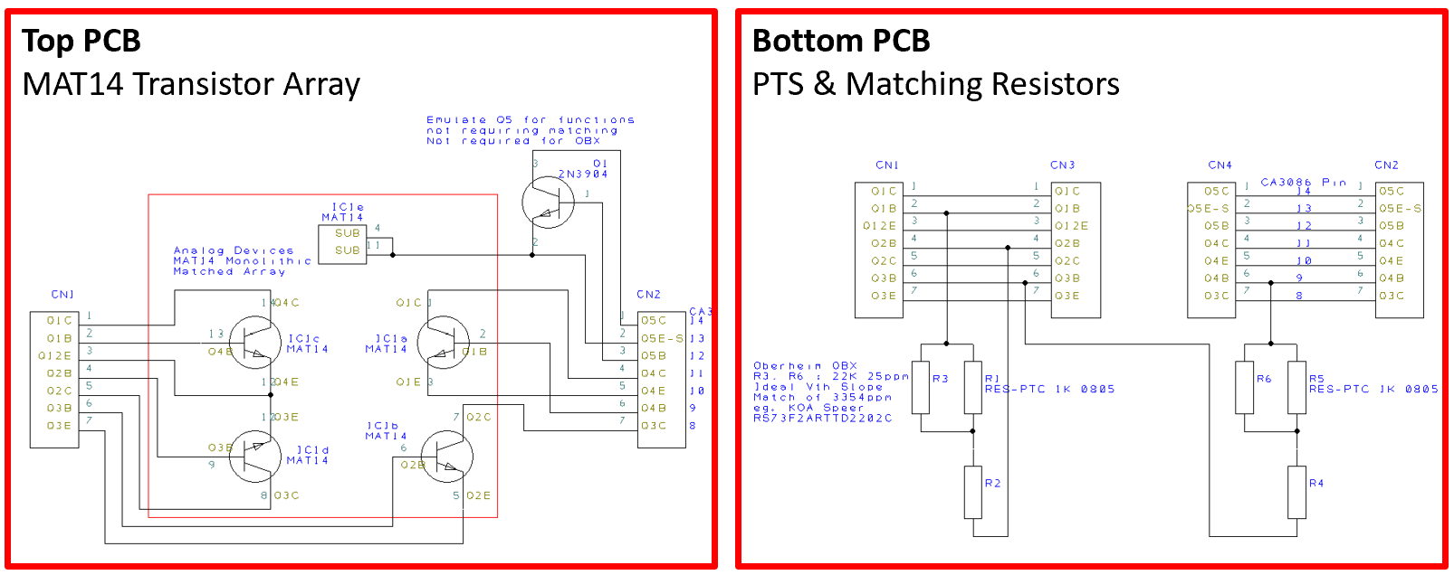
The TCRs in the OB-X schematic were placed in the appropriate positions along with series and parallel resistors. It was envisaged that the series resistors would be just links and the parallel resistor something to match the Vishay PTS to the Tellabs TCR.
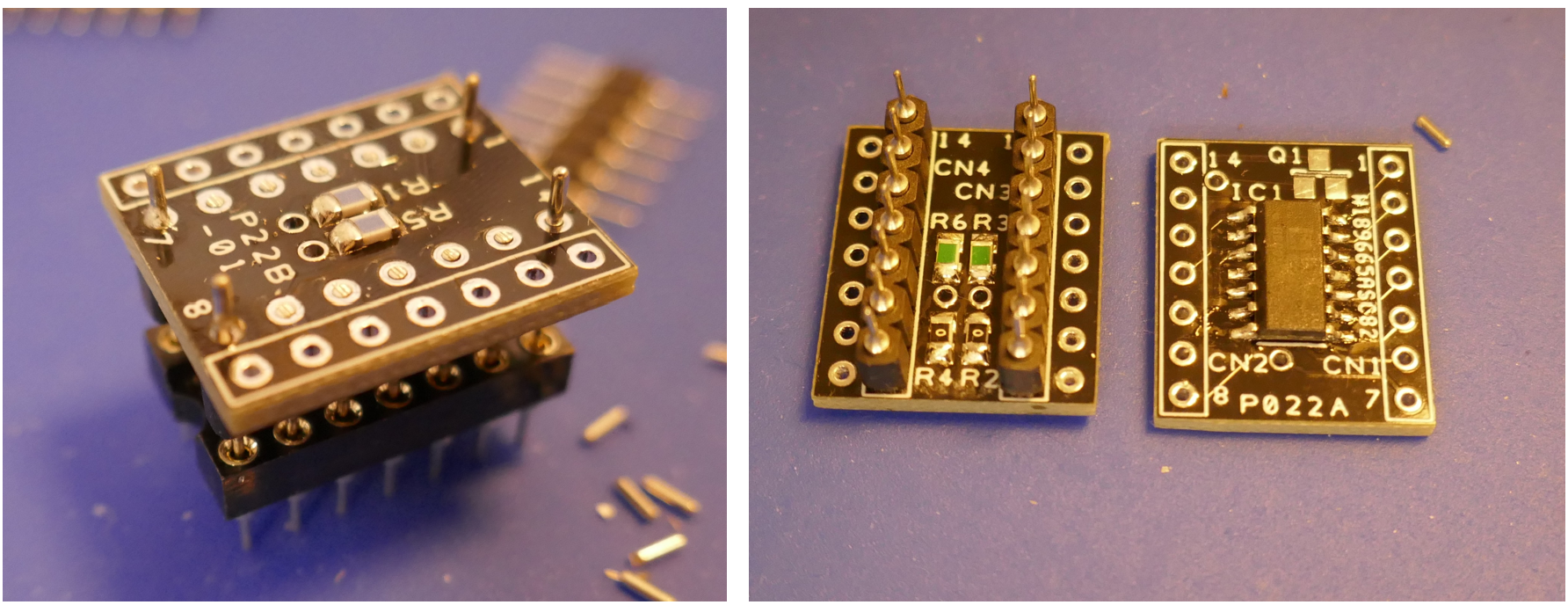
PCB is straightforward but fairly lengthy to make. I used turned pin SIL strips for the connections to the board via a turned pin socket and resistor legs to interconnect the two boards. The MAT14 was placed touching the PTS resistors using heatsink compound to make a good thermal transfer although probably not strictly necessary because the local temperature would be fairly stable in practice. The pictures below show the module with a full set of resistors, with the PTS in parallel with a 14700 ohms 25ppm 0.1%, that combined almost exactly match the Tellabs performance.
I created a model of the resistance vs temperature vs Transistor Vth slope vs Telllabs in a big spreadsheet. I was pretty excited to see that I could use a parallel resistor across the PTS resistor to match better to the transistor Vth slope than the Tellabs part, but it deviates frequency the opposite direction way when heated.
MAT14 Set-up
First test of the module resulted in an arrangement that was impossible to tune across the scale. It was caused by the MAT14 hFE being very high. A simple test using a potentiometer was placed instead of the 750K and it was increased in value until it was possible to fit the tuning at 440 Hz with the same control voltage as another voice at A1 Pin 6. Chose a mid range value within a tuneable range.
The “Hi-Track” adjustment was no longer needed with the MAT14 so was wound all the way so that -15V was on the wiper, depending on VCO1 or 2 it is CW or CCW when pot has been replaced with a multi-turn. Further tests with a frequency counter revealed a superb response across the entire scale in all transpose switch positions. However, it is vital to ensure the transpose switch circuit is accurately calibrated before starting. A cheap and cheerful 825K 50ppm 0.5% resistor was put in place ready for thermal tests.

A picture showing installation on a voice card is shown below, I had replaced all the potentiometers with multi-turn ones to preserve my sanity when calibrating. Even with multi-turn pots, sometimes a fraction of a degree still had significant impact.

Temperature Tests
A temperature controlled heat gun set at 50 C was used to warm up the module and a frequency counter was placed on A7 Pin 15 to measure frequency so that drift could easily be seen. Test was repeated on other voice boards, so I could compare.
With the old configuration the deviation at the start of heating was huge but relatively quickly started to correct itself and generally tracked the temperature once heat soaked. Results are shown in a table later on. The new module was much more resistant to change and took longer to reach final temperature, but overall was not as good.
The 14K7 resistors removed from the module, the scaling of frequency was different and as it was impossible to set up the tuning, just a temperature deviation was checked for. The deviation compared without the 14K7 was much less, being only 3 Hz or so at any moment, after heat soaking and left for a few seconds, it rapidly went to the starting frequency, showing promise!
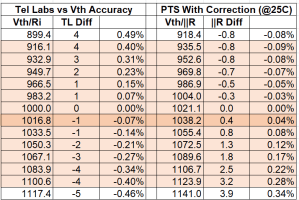
A simple calculation was made to fix this, compensating for the different value of PTS at 25C.

Tests were repeated on Voice cards B1 (original circuit) and B3 (MAT14 replacement), with the new resistors on B3 as shown in the picture below, the OB-X was fully tuned and they followed each other very closely.

The results table with everything described above is below:

Parts List
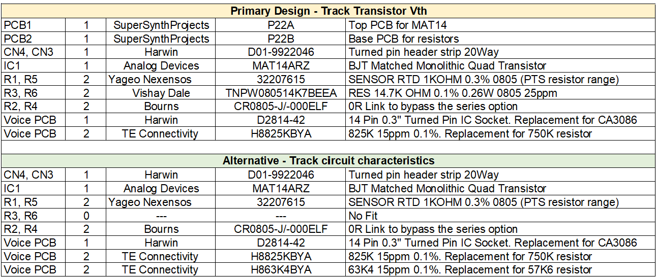
Two options are presented below, one that closely tracks transistor Vth and the other that was tweaked in line with the discovered characteristics of the particular voice card when heated, I chose the latter in the final installation. List below is in the Excel workbook.
Summary
Great results were obtained and we have a worthy solution to replace the old set up with new components, yet achieve a close match in orders of magnitude change.
- The testing was extreme, the circuit is unlikely to experience 50 C.
- As predicted, the new module changes frequency positively rather than negatively. The performance was like for like in magnitude meaning that none of the OB-X charm would be lost. In this restoration customer only wanted one swapping and was more than good enough. In an ideal world, we would put the same set up in all voice cards.
- There are many other temperature dependent variations in the voice card, although a parallel resistor across the TCR yielded an accurate match in modelling, there are other things we need to account for too.
- I think there are two solutions here, one with parallel resistor across TCR and if deviation is large then use no parallel resistor and change the 57K6 with 63K4 – depends on application.
- The 4 x uA741 op-amps get pretty warm and cook the original circuit, the new module stands the transistor array away from the PCB, having the op amps in sockets is also helpful.
- Replacing the uA741 amps with precision ones made no perceptible difference and caused more heating as they dissipate more power, this was identified as a bad side effect on the expo converter but definitely worth more work.
- In terms of absolute stability and accuracy, the +/-15V regulators are directly responsible for most variation, it would have been a bridge too far to put a precision regulator on this PCB in 1979, so we have to tune out manufacturing tolerance. The “Hi-Track circuitry is essentially referenced to the -15V power rail and the VCO ramp integrator is referenced to +15V.
Oberheim engineers did a fabulous job of engineering OB-X, OB-Xa & OB-8 synthesizers, I am really impressed by the quality of engineering and component selection for it’s time. I am blown away by the attention to detail in the analogue circuitry, for me it has been a fabulous “trip” into cutting edge electronic design in the 70’s.
I have PCBs if you want to make your own, contact me if you want some. I also have some completed & tested modules and resistors too.
Copyright © 2025 Super Synth Projects, Guy Wilkinson

You must be logged in to post a comment.