A fabulous 1980 Oberheim OB-X restored to it’s former glory, that had been toured with Supertramp and carefully stored for 40 years.
The owner of this OB-X has it available for sale, contact me if you are interested in purchasing it.

Why is the OB-X so special?
- Important historical synthesizer
- Does “Polysynth” sound in spades, it really is quite something
- The sound of certain patches & “less is more” turns out to be inspirational
- Discrete transistor VCO, quite unstable but in a good way
- No VCO is ever in tune at any moment, always slightly drifting, almost breathing by a few Hz.
- Analogue portamento across all VCOs sounds unusual and addictive, each is slightly different.
- Most parts still readily available, or at least alternatives and remakes are available.
This article is intended to help other technical people deal with some of the key areas during refurbishment or tuning, or maybe you have a remake and just need to understand some key areas better. I have created a couple of small projects around it to deal with some parts that are no longer available or where some improvement is needed.
Oberheim engineers did a fabulous job of engineering OB-X, OB-Xa & OB-8 synthesizers, I am really impressed by the quality of engineering and component selection for it’s time. I am blown away by the attention to detail in the analogue circuitry, for me it has been a fabulous “trip” into cutting edge electronic design in the late 70’s, It has been a privilege to have had the opportunity to fix this classic instrument.
Approach
It was a very large task to restore this beast of a synthesizer and required “shot-gunning” most parts. It took over 1 year to research & restore in around 220 hours, had I had this guide, it would have taken much less time, maybe 140 hours.
A project spreadsheet was prepared to help manage the colossal undertaking of this job. Being mindful of it’s age and quality of integrated circuits in 1980, unless all ICs are replaced, it will develop “gremlins” as time passes and need periodic attention.
The spreadsheet contains a ratio-metric calculator for swapping potentiometers on voice cards, including a voice card checklist. If you choose to do it this way, the instrument will be almost in-tune or configured once you begin that process and makes life a little easier, it was particularly useful for the control board. It was found to be good doing one voice card this way, so that others could be compared with it. I did them all so I could check for differences and try to notice any inconsistencies that could identify a weak transistor or amplifier, because this unit had clearly been serviced many times and parts replaced.
Wherever possible I always avoid new old stock (NOS) parts as they have a shorter life than a brand new part, the spreadsheet contains some recommendations that worked superbly well for me.
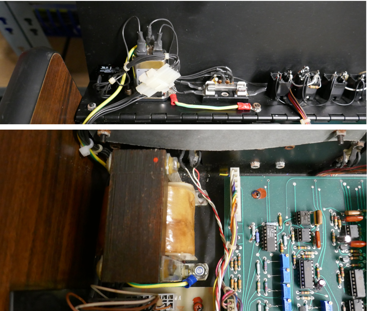
The initial inspection on opening the OB-X is shown below, it had a Patch96 modification from the 70’s designed by J L Cooper, it is mounted to the right of the front panel.

Resources Created
- Project Information Spreadsheet – OB-X Project Information-V1.xlsx
- Initial Factory Patch Data – Oberheim OB-X Factory Patches YouTube.wav
- Factory Patch Data Re-Recorded – OB-X Factory Patch Data.wav
- Recordings of Factory Tones – Oberheim_OB-X_factory_mp3.zip
Logic ICs
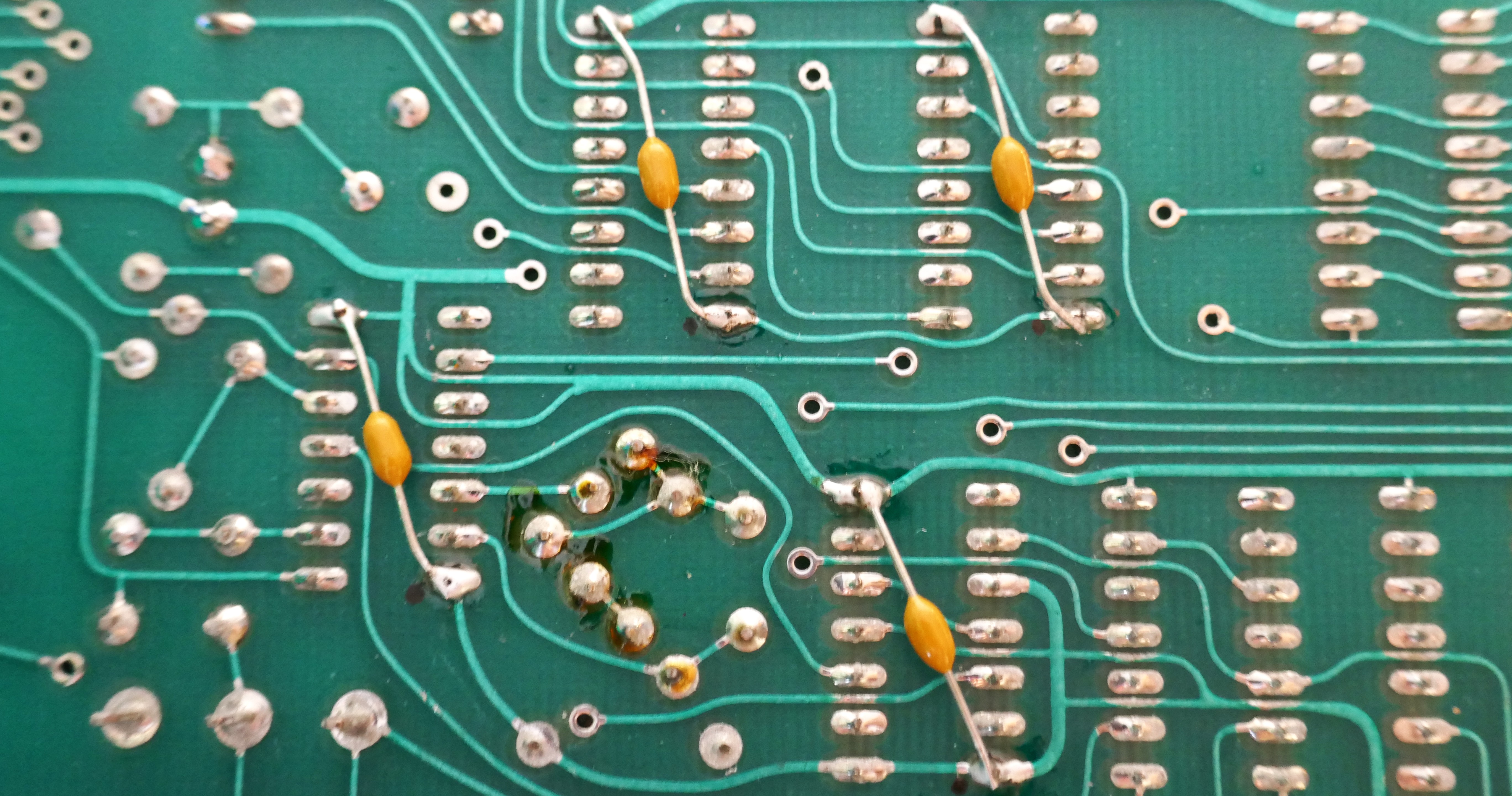
In many cases 74HCT can be used instead of 74LS and will reduce the current consumption dramatically, however when doing this, it is good practice to add an axial ceramic decoupling capacitor on the underside of the IC. Modern ICs impose greater dynamic loads when switching, that could lead to misbehaviour of the processing system. It is also better to use new modern parts. In this case we also replaced the Z80 with a modern CMOS part. Overall, heating was much reduced that helps keep tuning stable. The picture below shows an example section where capacitors have been added on the underside across the power pins of replaced logic.
The project spreadsheet has a list of logic and analogue parts ordered to get the main board system up and running. It includes a few other ICs, axial ceramic capacitors and regulators as well. It is not an exhaustive list but a great one to get started with the basics. In this unit, 34% of the ICs had shown to have failed when removed and placed in a logic IC tester. Getting the processor up is not expensive, that comes later as the analogue circuits are debugged! Later on, the Z80 and memory ICs were replaced with new modern parts, see later sections in this article. Getting this up and running with voice cards disconnected means that you can get everything working, generating the right control voltages.

Memory
EPROM
The chips are ancient and require +12V, -5V as well as the usual 5V. These are horrible and I avoided them like the plague for my robot projects in the 80s. There is a ROM hack shown on Retrosynth showing how to convert them to a single 2732 EPROM. In future I may create a simple board that will take a modern EPROM to future proof it and avoid PCB modifications. The EPROMs are only rated for 20 years to hold their program data; they would be well overdue for a refresh.
RAM
There are two types of RAM used in the design that are no longer available. I would not bother replacing them with old, they will likely fail.
Patch Data : HM-6508 1024 x 1bit low power static RAM, using 4 ICs to make a 1K by 4 bit
Working Memory : AM2111 256 x 4 bit static RAM using 2 ICs to make 256 by 8bit

I chose to replace the RAM with a set of PCBs in this project, Oberheim OB-X Memory Replacement that also corrects bus contention when using modern parts. You can have FRAM or RAM options for patch data, FRAM does not require the backup battery in the PSU and is cheaper than the recommended battery.
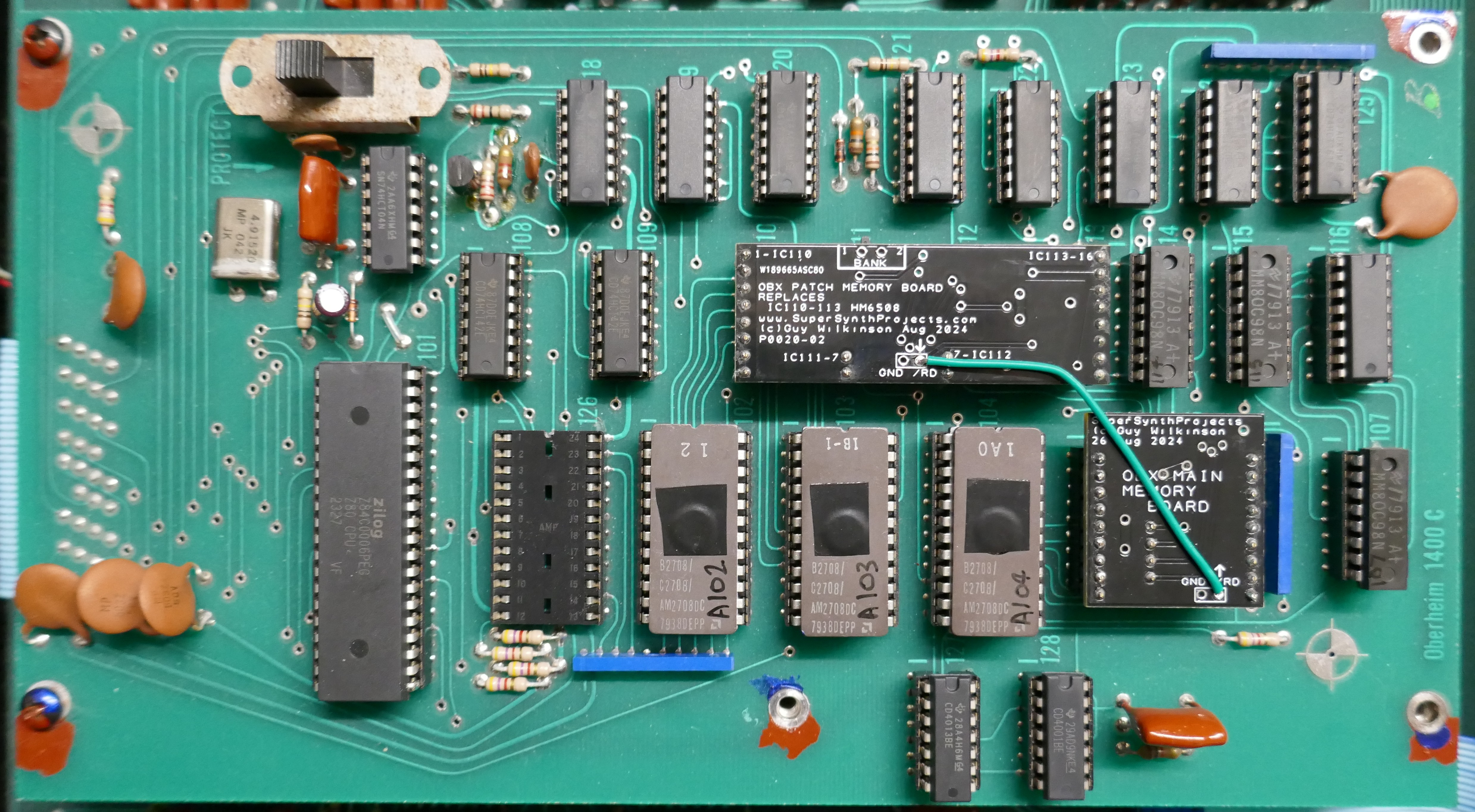
Looking at the processor board above, I initially found it unusual that there are very few decoupling capacitors.
Analogue Components
Here is a few hints and tips on component replacement, it can make a great deal of difference.
Operational Amplifiers
Many 741 op amps are used in the voice cards for the control circuit and are low bandwidth which is ok for this part of the design. They were replaced with new LM741 devices that seemed to improve the performance, probably down to modern manufacturing processes. A trial was done to replace these amplifiers with precision types OP07 & LT1494. They didn’t improve pitch stability in any way, even when heated with a hot air station, because they are not the dominant factor. LM741 dissipated less power, so were left in the design. If precision types are used, the voltage regulators have to be upgraded, leading to an ugly modification.
Audio and control paths use TL081, TL082, TL084 amplifiers everywhere because they were a low cost alternative to the TL07x types in the 70’s. Although you can buy the TL08x parts, they are exactly the same as TL07x these days, just different labeling. Replacing these amplifiers with modern TL07x is the way to go.
The service manual shows KEYCV circuits as having CA3240 (eg. A54) but these were later changed to TL082 for improved performance, replace these with modern TL072.
Pitch bend circuit benefited greatly from the LT1946IN (see other section) rather than the LM324, but not anywhere else in circuit.
Trans-Conductance Amplifiers
There are a 52 x RCA CA3080 amplifiers used in the design, many had failed. Ones that had failed or degraded were replaced with AS3080 remakes. I chose to only replace faulty ones, but over a period of 1 year of refurbishment, 5 failed during tests even after the OB-X had been put back together. It is definitely recommended to change all of them if never replaced. The main issue for me was that they often still functioned but degraded and led to changes in the character or difficult to control.
Voltage Regulators
Replace like for like but ensure that the tabbed ones are high current types with a thick tab, such as Texas Instruments LM340 series. The 78L and 79L regulators are fine for the voice boards but note that some may have higher ripple than expected and would need to be swapped out. Using a scope on AC voltage, it is easy to go around all rails and check for excessive ripple, you are looking for no more than 20mV of noise with occasional switching spikes. Faulty ones tend to oscillate at about 6 KHz that had audible effects. Out of 20 of the new regulators purchased, 4 were found to oscillate (within spec however!) and impact the sound quality of the affected voice cards. Excess regulator noise causes the comparator circuit in the VCO to trigger at random points and cause pitch distortion and bad PWM output.
Transistor Arrays
The voice boards use CA3086 transistor arrays. They can be substituted for CA3046 too but I chose to use MAT14 on a small adaptor PCB and the project to show how this was done is, Oberheim OB-X Expo Converter. Note that the CA3086/3046 are available as NOS devices from AliExpress but I was too afraid to try them for fear of fitting something old, fake or inferior.
Tempco Resistors
For pitch stability as the unit warms up, the TCRs used in the exponential converter are important. OB-X uses Tellabs TCRs, 1000 ohm 3500ppm 1%. I dug deep into this area for fun, the conclusion was kind of unsurprising, you would think that finding a TCR as closely matched to Transistor Vth would be the best way, but is not so in this circuit.
I made a project to replace this set up with high end modern parts, Oberheim OB-X Expo Converter. I achieved similar & very close performance, overkill design but it is an OB-X and none of the characteristics are affected, just better resilience to reliability & heating effects.

Capacitors
Resistors
Trimmer Potentiometers
DAC – Don’t Modify!
The Digital to Analogue Converter (DAC) DAC1020NL is in the heart of the system operation, without it very little can operate properly. It is also used to generate a signal to make a comparison with analogue measurements via comparator A36. It is a very economical way to make a 10-bit ADC but loads the processor quite a bit as it performs successive approximation by presenting numbers on the latches A34 & A35 and looking at the result on bit LR7. Putting an oscilloscope on Pin 6 of A37 allows you to see this action happening, it is also a great way to take a look at the front panel control signals as a composite signal.
A modern like for like replacement could be the AD7533, it looks identical, I didn’t have chance to try it as a replacement, let me know if you tried and were successful. There are a lot of NOS DAC1020NL available but these are old parts with shorter life.
The software saves some time when in patch mode by not wasting time sampling the front panel controls, that happens only in edit or manual modes. This must improve the keyboard response times too. I also noticed that for the cleanest audio path, patch mode generates less noise, see master tune modification in this guide.
Adjustment of the DAC via T9 is essential before any other work takes place and if any voltage regulators have been replaced (even though there is a reference diode used in the design). Service manual is great in this respect.

Potentiometers

Test the potentiometers before refitting using a scope and power supply across the track, set current limit to a few milliamps to avoid a mishap if connections are put on incorrectly. Pictures below show no spikes on the traces indicating a clean track.

Master Tune Control
Minor design flaw when in Edit or Manual modes, discovered excessive noise on master tune circuit arriving from the potentiometer. This is a high impedance circuit and subject to crosstalk from the scanning circuit arriving from MUX switching. I added an axial ceramic 0.1uF capacitor (same type used for decoupling replaced logic) to the board to eradicate before the value goes to the dead-band network (2 diodes).

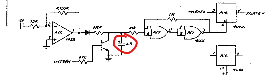
Pitch Bend Control
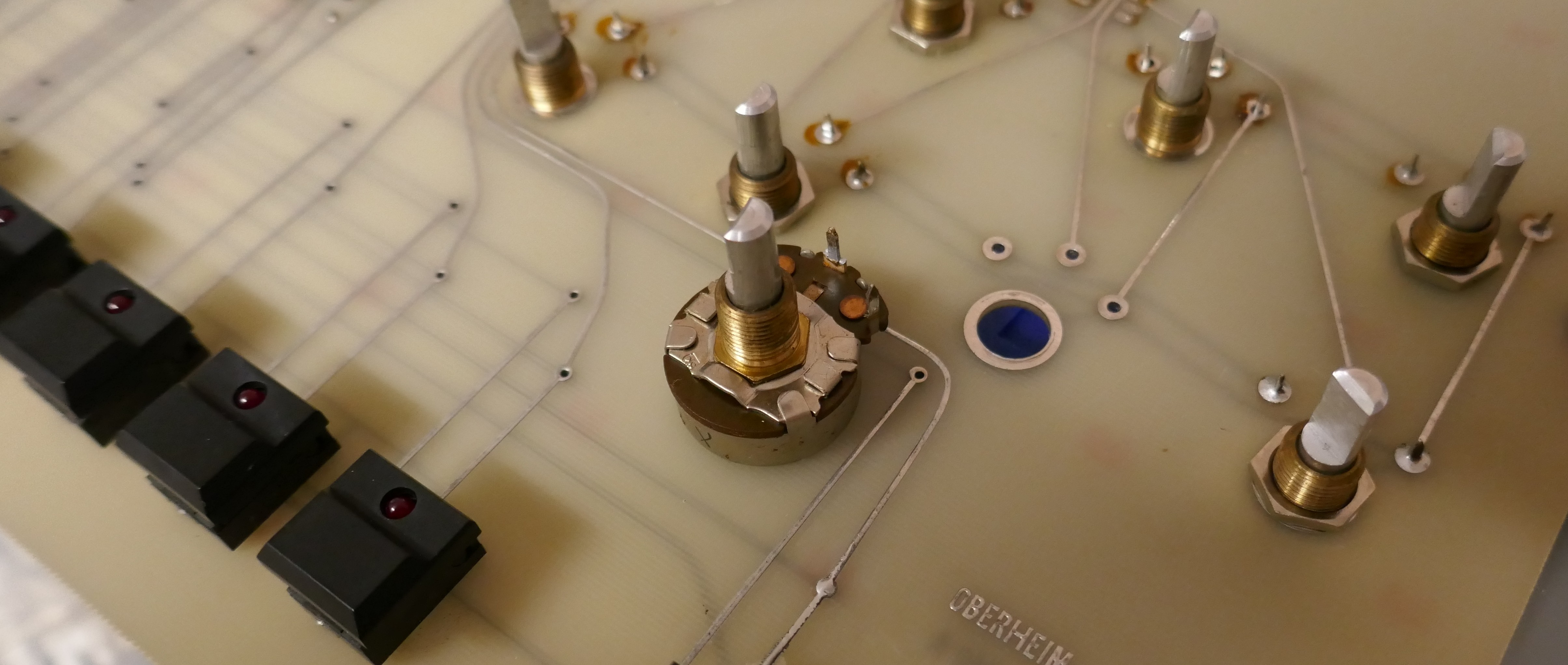
The Pitch Bend control can be a major contributor to poor tuning if it is not set up correctly or the mechanism or potentiometer brush is badly worn. It can cause a slight pitch offset whose value depends on which direction it moved from last time it was used. Also, there is a lack of symmetry in the amount between extremes of movement, this can be accounted for by adjusting the end stops, but still did not perform correctly in practice. Pictures below show the assembly and the inside of the potentiometer:

After two hours trying to improve the assembly and remove errors, an electronic solution was required; increase dead-band and improve the amplifier. Incidentally, the use of dissimilar metals in the design results in it welding itself together, the mechanism was impossible to strip down in this case.
Increase Dead-band
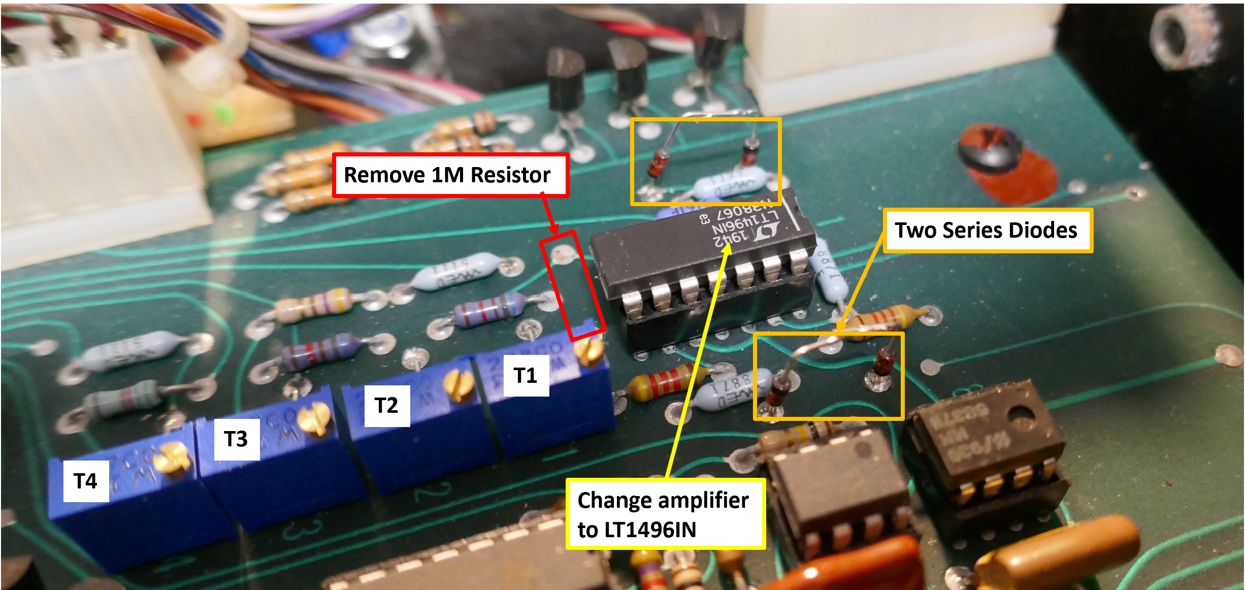
To compensate for a heavily corroded and no longer adjustable mechanical assembly. Add additional 1N4148 diodes in series with each diode connected to pin 1 A1, this increases dead-band region to accommodate worn out brush inside bender potentiometer. This also reduces leakage currents from adding input offset to the value, improving tuning. I did try Schottky diodes with a forward drop of 0.3V but was not enough drop in my case.
Accuracy Improvements
Changing the amplifier for a modern precision one, meant that another problem occurs: the range is different in each direction, in original design some compensation was added to account for poor quality amplifiers available at the time.
Change the IC A1 from LM324 to an LT1946IN higher precision Op Amp, this made a difference on input offset of 2mV, that was noticeably better for pitch stability around the dead-band region.
With a better amplifier, the 1M resistor on input pin 6 needs removing as bias currents are lower and performance of circuit is now perfectly symmetrical. I was really pleased with these changes, it made such a difference. The diagram below shows the modifications required:
Pitch Bend Calibration
Set T1 by monitoring A1 pin 1 and setting so that moving lever from each direction leads to a voltage magnitude that is equal from either direction, in our case around 480mV. I think this represents the side to side movement of the brush inside the potentiometer or mechanical slip in the mechanism. Set T1 and T2 to exactly 1.000V away from norm (output pin N1) when octave switch in down position. Set bender to “Narrow” and set T3 so that output pin N1 is 0.167V.
Before starting Voice card tuning, ensure the voltage at A1 pin 1 is a close to zero as possible and touch the bender to ensure it reaches as close as possible. Do not touch the pitch bend lever again until tuning completed.
Test Switches
- Power on – FTA & FTB are at random values, they are not recovered from persistent memory!
- Press Auto switch and all VCOs in all voices are are tuned in turn.
- If a Voice board does not calibrate, it is not disabled
- Moving right test switch down position instantly returns FTA/FTB to mid point values, returning it, values were maintained until Auto switch pressed

Control System

Tuning Hints
- Different quantities of voice cards skew the filter tuning due to loading of the OP amps.
- Spacing the top motherboard away from bottom one helps keep tuning stable.

Critical Items before tuning
- Calibrate DAC
- Calibrate pitch bend & leave in zero position after confirming zero volts, check A1 pin 1.
- Set Master tune knob mid-way and ensure voltage at potentiometer wiper is as close to zero as possible, this is a good point to adjust the position of the knob too.
- Calibrate octave switch, each position of switch should offset by a difference of 1.000 V from centre position. If this is correct then it means that it can be used to get voice card properly tuned over wide range.
- Test switch 1 in down position (when lid open) sets fine tune FTA/FTB outputs to mid position, confirm & check at each voice card.
- Manual mode with Oscillator Frequency controls fully CCW
Voice card set up
- Confirm with scope that +/-15V rails are smooth and not have excessive ripple/oscillating.
- If pots are new or not been ratio-metrically replaced, then set them mid position before installation.
- “Hi Track” adjustment is a devil to make work. Replacing all amplifiers with modern manufactured parts made it not required in this case.
- If not using “Hi Track” adjustment: Potentiometer on VCO1 & 2 should have wiper to -15V on voice card supply voltage. When using multi-turn pots: VCO1-Fully CW, VCO2 fully ACW.
- If using “Hi-Track” adjustment: Potentiometer reads 3.717K from wiper to either end when in mid position due to 10K across the track.
- Confirm that FTA & FTB (fine tune adjust for VCO1 & 2) are mid range (on mine 2.671V +/- 0.1V) before calibration when test switch in 1 in down position (power cycled). Connector A pins 1 & 3, 2-Gnd can be easily checked with DVM for this. Note that mid position FTA/FTB values can depend on reference supply voltage that varies a little between instruments.
Auto-Tune Circuit
It is essential to complete all voice card tuning and calibrate all DC output offsets to zero before testing Auto-Tune functionality, otherwise it will just fail at each point. Some versions of software will block the use of a voice that does not tune and other versions, the voice just carries on regardless, that I prefer as you can disable any sick voices with the 8 way DIP switch if that is fitted.
In this instrument, Auto-Tune data did not appear to be stored in the patch memory, nor did it get passed out to the tape interface.
Tape Input
Mains Input
Keyboard Metalwork
The keyboard is a Pratt Reed arrangement with J-wire contacts. There are many YouTube guides on these assemblies and we don’t repeat that information here, however there are a few additional discoveries and pointers.
It is strongly recommended to remove the PCB first before working on the metalwork. Great care needs to be taken when removing the PCBs to avoid bending the J-Wires any further.
 Springs and keys are easily removed from the key bars. In this assembly, red springs are for black keys and black springs are for white, check spring types before disassembly and refit correct spring type.

Painted the keyboard assembly and key bars with black acid etch primer. This keyboard was very uneven, so the key stops were realigned with a spirit level even though further adjustment would be needed later (in all dimensions! I hate these keyboards, give me a Matsushita JD800 one any day!).
Stripped the corrosion from the key bars using a stainless steel wire brush attachment for a hand drill, except on areas that touch the bushing sides unless badly corroded. Avoid getting paint on the inside of the key bars to avoid rubbing on the bushing unless surface is badly corroded.
Polished all the white keys to remove deep scratches using T-Cut and a cotton polishing buffer. Black keys had a minor hand polish so that their colour didn’t change, a more gentle approach was used for them.


Fit all keys and before putting screws in, align the front placement using a straight edge (600mm spirit level). Once assembled but before screws attached, move key stops slightly to level off the white and black keys. You may need to realign the key stops to make the keys positioned evenly in all directions. Attach all screws for the keys and conform alignment as you go.
Keyboard PCB
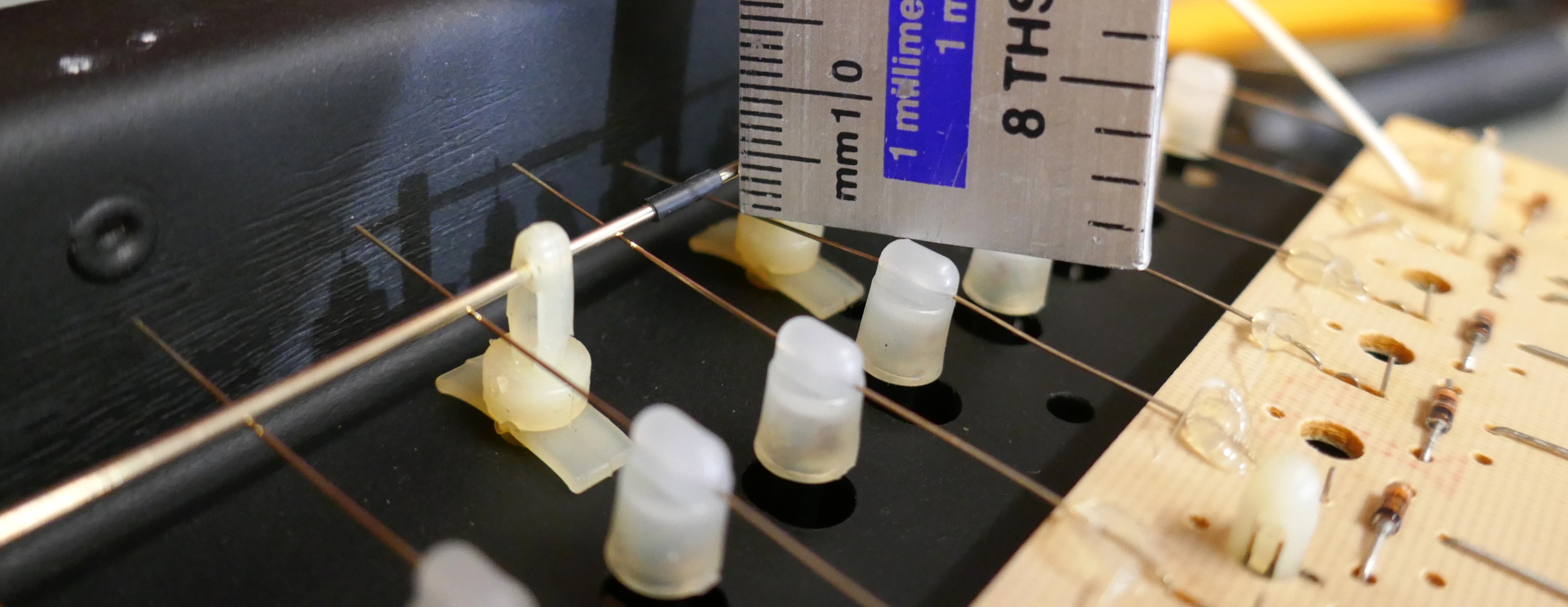
Clean bus bars just using IPA, if plating looks badly worn and if keyboard had intermittent behaviour, it is possible to rotate the bus bar slightly by 90 degrees to use a non-worn area, the bar is soldered in so will not move unless the solder attachment is heated with an iron.
Gold wires on PCB cannot be rotated but they can be cleaned with good results, they have a brushing action so should be ok with a clean. This is an incredibly fiddly process and very easy to damage the contact wire, they are irreplaceable. It is also possible to re-plate using a gold plating kit, but confirm that diodes on the assembly are still working after this procedure. Clean the J wires on a clean flat surface.
Build up the contact assembly with a 3 to 4mm clearance between contact and bus bar when in rest position. This is done by adjusting the plastic grip up and down on the actuator that the gold wire threads through. Obviously do this without any keys pressed from being upside down.
Once completed and tested, lubricate the fulcrums and contact points for springs, check alignment. Total nightmare but it can be tested outside of the instrument.
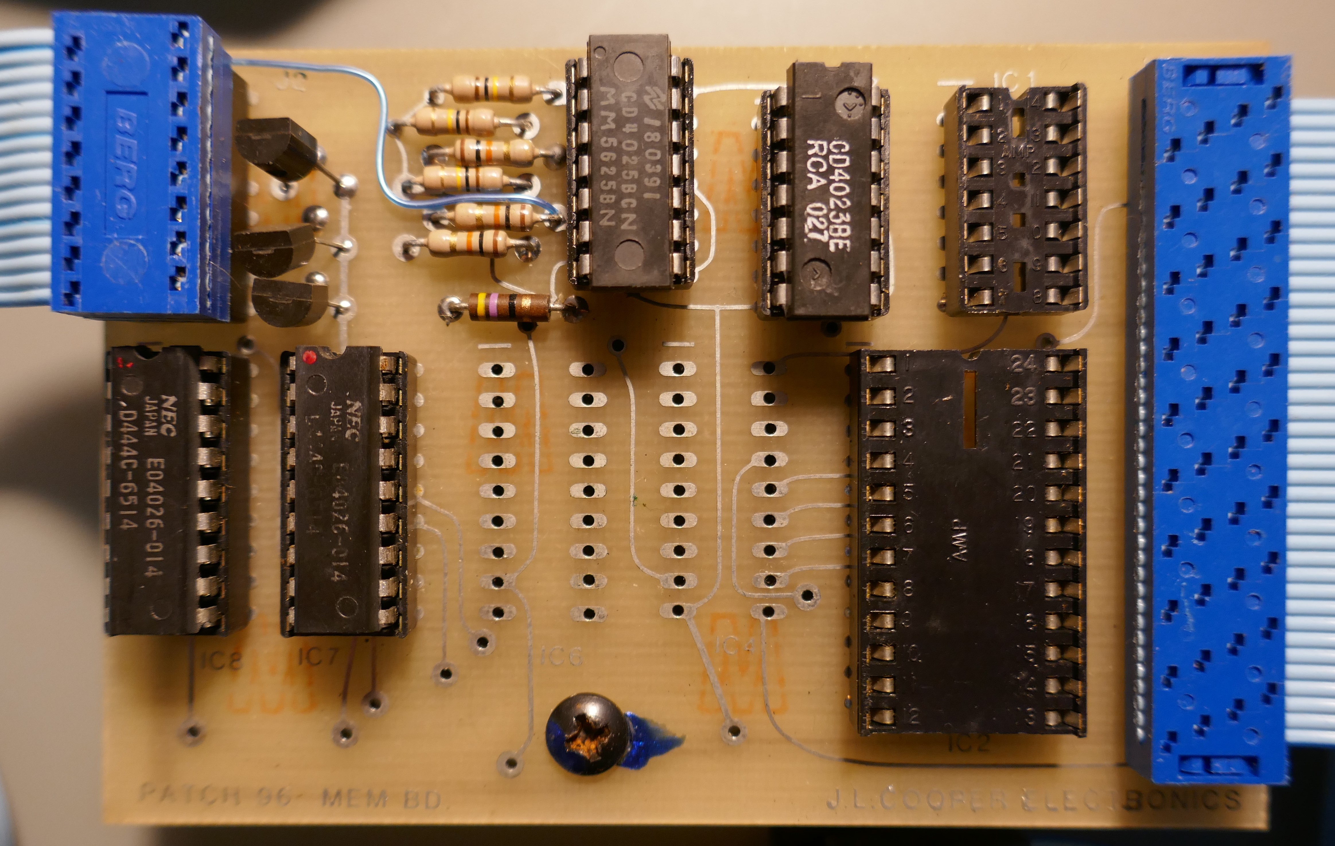
Patch96
A patch storage extender for the Oberheim OB-X designed by J L Cooper was sold as an upgrade in 1980. This was removed from the instrument but could have been upgraded with an FM1808B-SG and some fine soldering. It is described here for historical reasons, quite an interesting upgrade.

The control panel was mounted on the right of the front panel and memory board was attached to the CPU board and plugged into the expansion connector and RAM select logic IC.
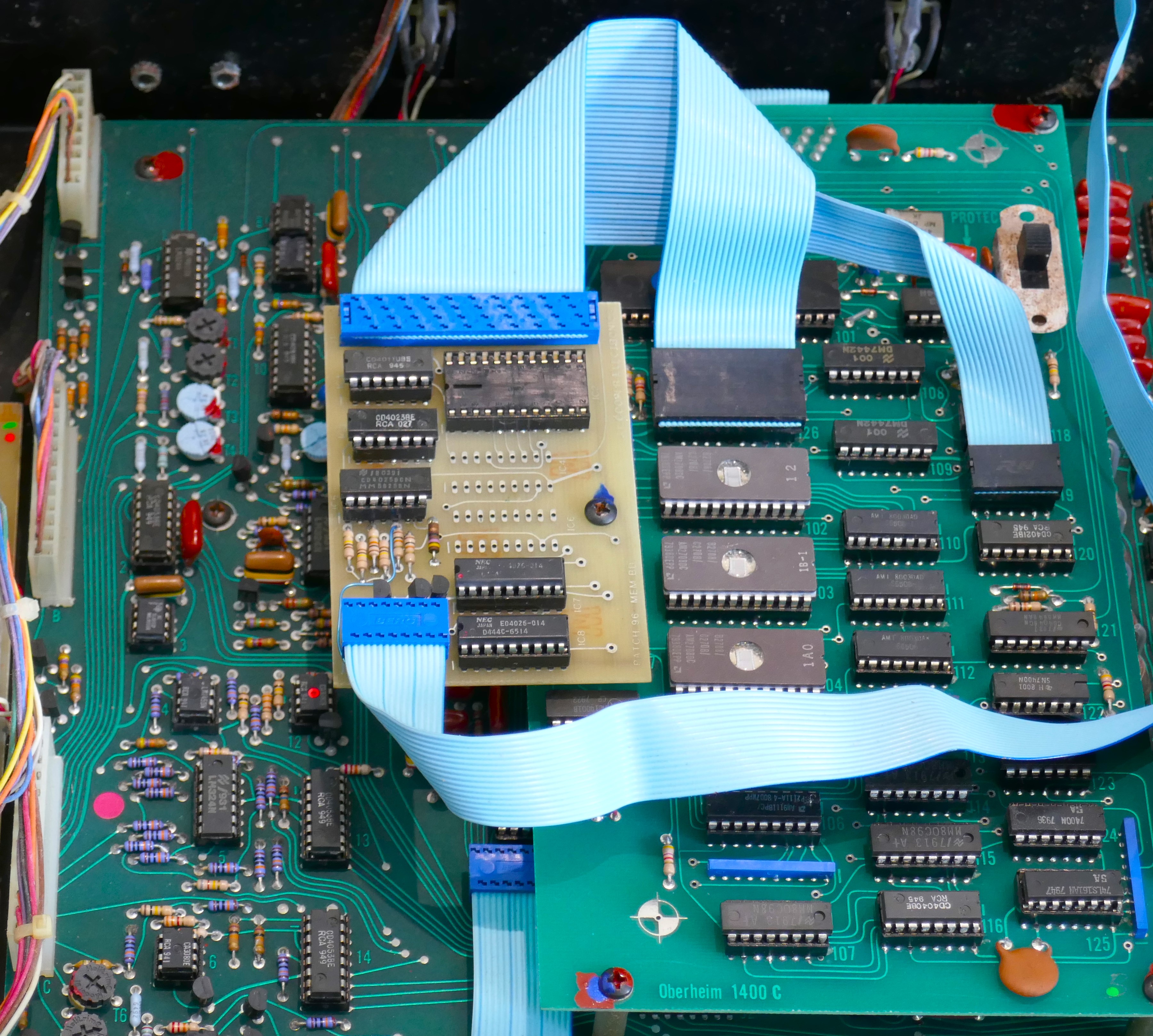
The design used memory ICs that were NMOS technology and put a huge drain on the internal battery. At the time, with limited memory options available, there was not any other way. The Patch96 RAM chips consume 24mA in low power standby mode, a lithium battery would not last very long with this add on as it was in 1980.
On the CPU board, patch data is stored in the 6508 low power 1 bit memory chips (for battery back up) controlled by A119 MC14011B. The Patch96 unit simply replaces the enables to these chips and present to bus via A126 socket (expansion connector) that has the address/data bus connections and other signals. A119 MC14011B is transferred to the Patch96. Software on the ROMs was unchanged.


You must be logged in to post a comment.