This is a DIY project that can be used to rescue a terminal SuperJX when the transformer has burned out. It has been installed and long term tested on JX10/MKS70 and a bare PCB is available. It also has many other potential applications in other synths or modulars.
The power supply is also available ready built from Plasma Music where fitting services for various other upgrades is also provided.
Replacement JX-8P Power Supply
Latest version P0004-04 PCB accommodates replacement of all JX-8P power supply components: Filter, transformer & Linear PSU. Bill of Material contains all variations and options for different display mods plus the JX-8P version. When installing this, it is strongly recommended to perform a modification to the chorus circuit shown in the SuperJX Maintenance Section.
Pictures of the new version of PCB, can be found here.
Why Did This Come About?
This design was inspired and sponsored by Peter Connelly. The JX10 plays an important part in Peter’s professional work, take a look at his website.
Many thanks to Peter for providing the persuasion, encouragement, faith, trust, funds and requirements into this design. His SuperJX was in trouble and needed some very special help!
Fitting inside the MKS70 has been pioneered by Keith Meiere & Juha Forsten, see the build & fitting recommendations for details of their work.
What Does it Do?
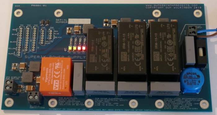
The board provides a full replacement of the mains filter, transformer and power supply for the JX10 and MKS70, that has ultra low ripple, no dry joint degradation, no limited life capacitors, runs cool and automatically uses any mains voltage from 110VAC to 240VAC. The design is focused around power converters with added power filters to remove switching noise, essential for keeping disturbances away from the audio path.
It is rated at roughly 1.5x the average power consumption needs of an upgraded JX10 so runs without stress and supports upgrades without generating excess heat.
Specifications
- 195 x 110mm to fit inside MKS70 or JX10
- Single Board solution replaces Transformer and Power Supply Board
- 110-240V 50/60Hz AC operation
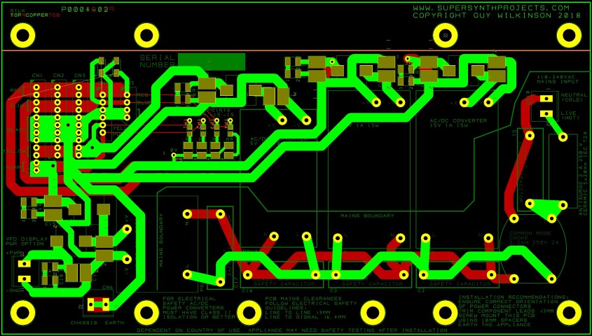
- PCB safety clearance: >3mm line-line, >6.4mm line-chassis/signal
- T2A 250V ceramic fuse
- Mains filter
- +5V 1.5A
- +/-15V 0.6A
- +9V 0.55A for VFD display upgrade & PG800
- Short circuit protection
- Power rail indication
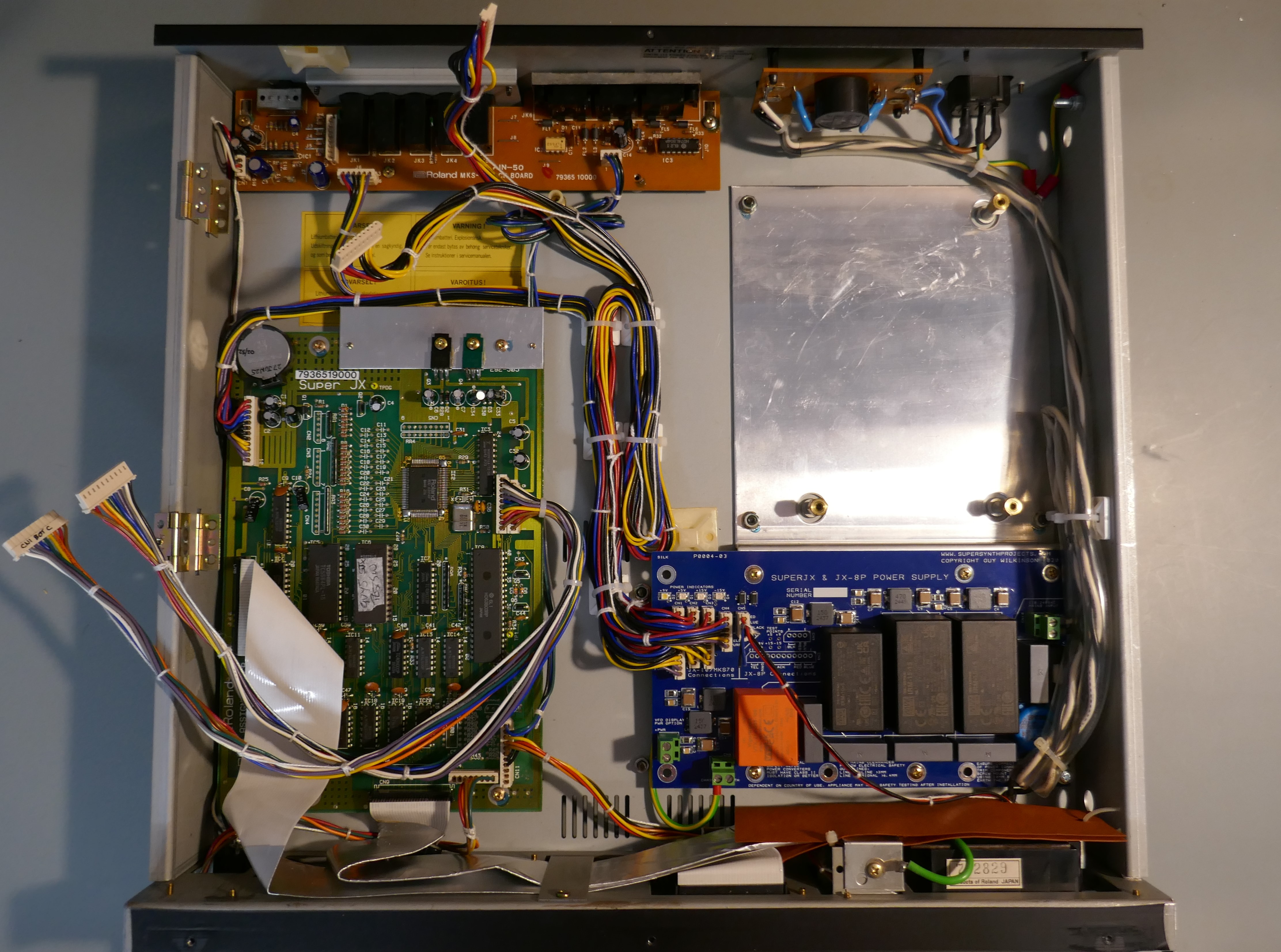
Multiple mounting options are provided to replace the power assemblies inside the two different instruments. The MKS70 has the transformer on the left, the JX10 on the right. JX8P versions fits in a similar way to the JX10.
PCB from SuperSynthProjects and components from Mouser or Farnell cost approximately 160 GBP. This is good value for a DIY project when replacement costs of secondhand transformers are well in excess of this.
Differences
It differs in functionality from the Roland design:
- No tracking regulation
- +5v logic power is not proportional to the +15V power rail
- Requires the instrument to be earthed
See the design description for further details on why these are not deemed an issue.
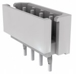
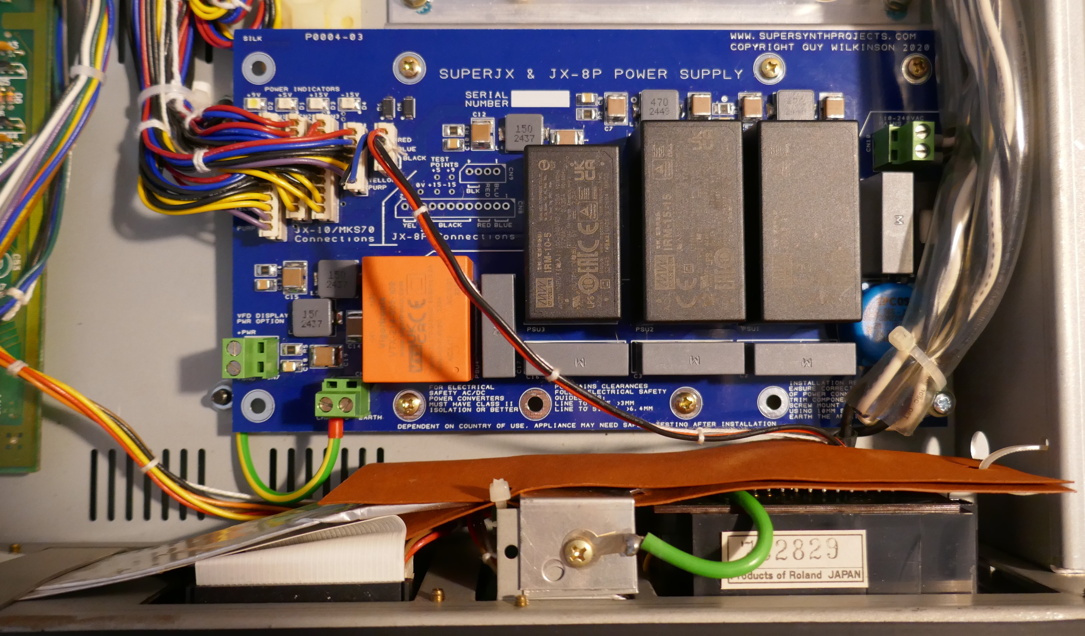
Connector System
Original specification connectors (Molex SPOX 5267 Series) can be sourced from Digikey and Mouser, some of which are slightly different.
Many thanks to Murray at Kiwi Technics for pointing out the availability of these parts and to Keith at JX Zone for performing trials and pioneering fitment in 3 different instruments.
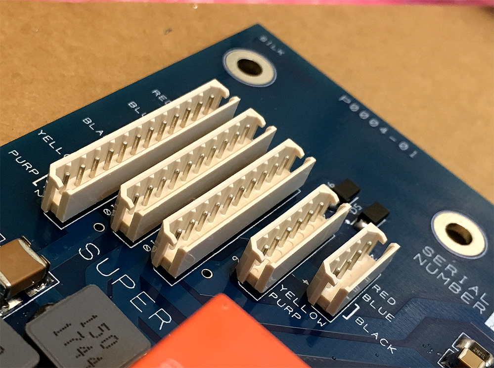
If proving difficult to source, instructions are shown for removing the old 2.50mm pitch connectors from the original Roland power supply board.
The PCB has holes large enough to accommodate the slight differences in pitch, therefore a 0.1″ Molex system will fit. Pins and wires can be refitted with suitable housings and terminals.
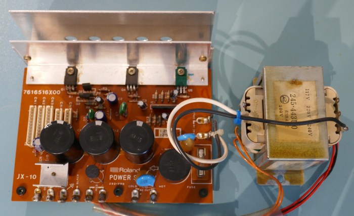
Roland Power Supply Design
The power supply in the Roland SuperJX is a really great design and when working well, delivers a lot of very stable power to the instrument circuitry. The linear design means that it has a low output impedance maintaining tightly regulated supplies to the analogue circuitry. The only disadvantage is that it generates a large volume of hot air inside the instrument.
If the transformer is working, then technically there is no need to replace the old power supply. If rebuilding or repairing the Power Supply Board to original Roland specification, this full guide on the maintenance page explains how. The advantage of repair or rebuild is that it is exactly to the original Roland design, one disadvantage is that the regulator IC is only available as “new old stock” (circa 1986) and could fail in a horrible way, where it fails to regulate and can place high voltage on sensitive circuits.
Losing a 12 voice analogue instrument like the SuperJX is considered a tragedy and as the transformer is unobtainable, this project is a fantastic solution when it fails.
JX-10 Fitment
The project was developed and tested using a Japanese specification JX-10 that was converted to UK specification. It is a fully upgraded instrument with enhanced VFD and Vecoven PWM.
MKS-70 Fitment
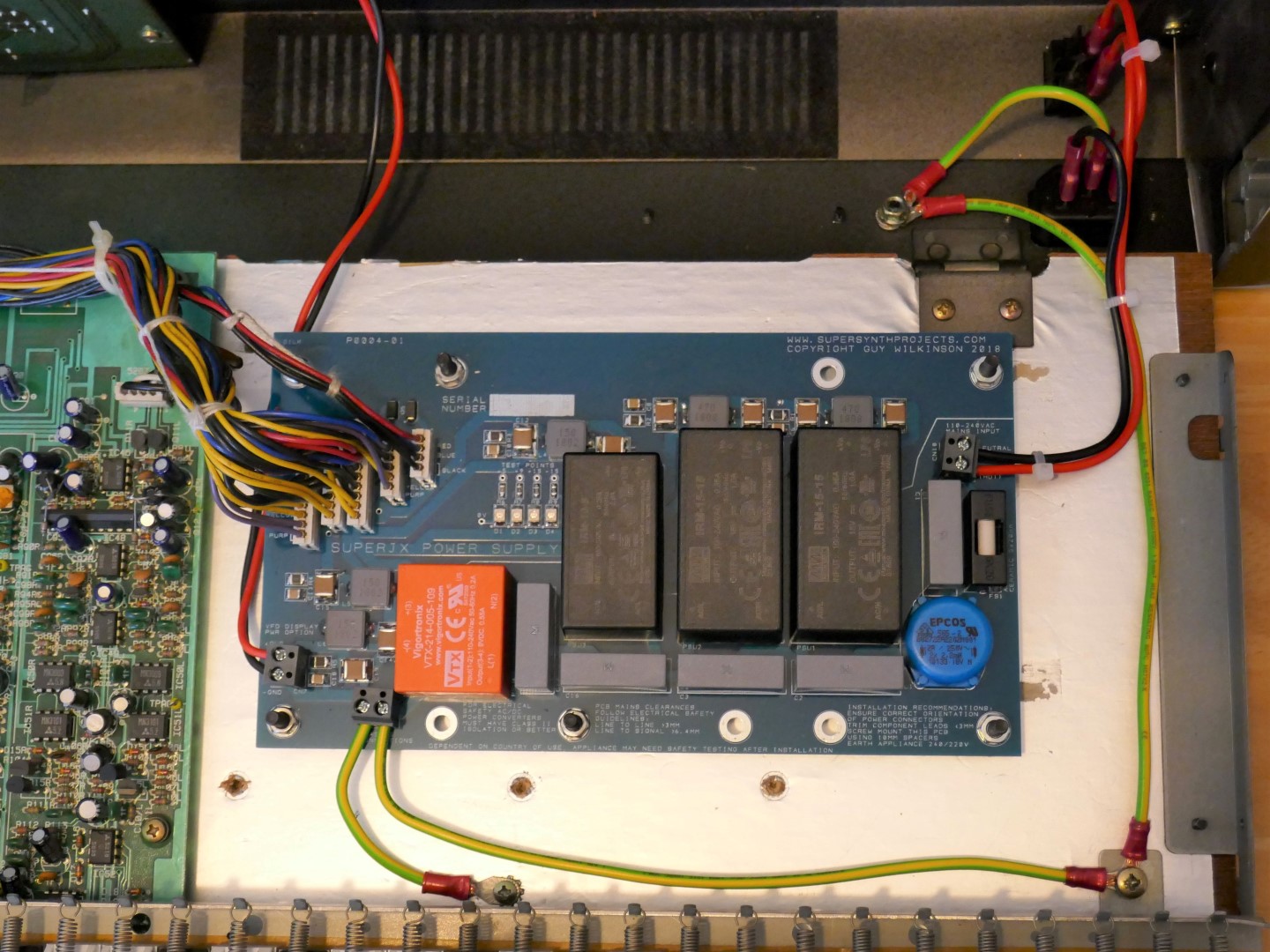
Below is a picture of it installed in the MKS-70 using preexisting mounting hardware, the heat sink plate is reused to maintain enclosure rigidity and the mains filter is kept in place but with an upgraded 2 Amp slow blow fuse. Note also that the wiring layout has been optimised for noise reduction. An article is shown here for that arrangement.
A close up view of the fitting is shown in next picture, note the incoming mains wires are not reduced in length, just in case we want to reinstate the old PSU.
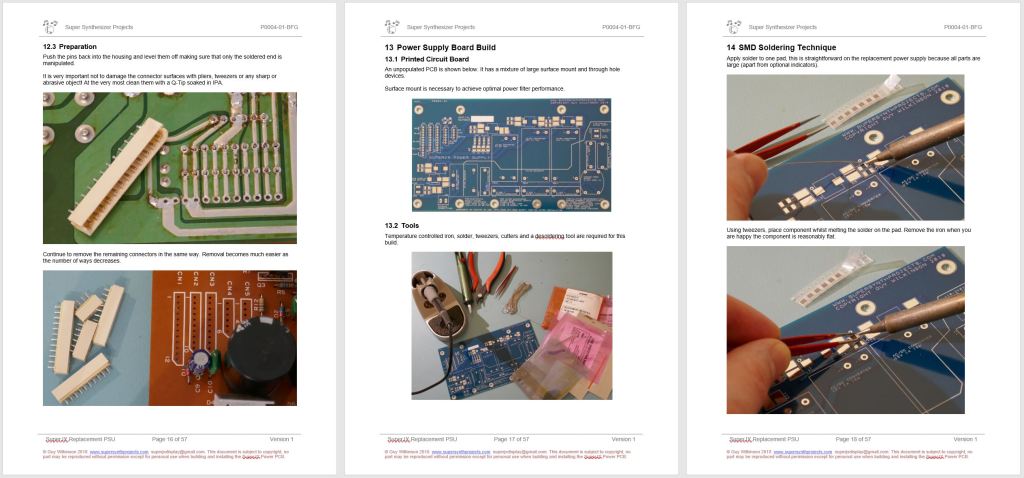
Building a Power Supply
Experience of electronic construction and mains appliance wiring are essential. Full design calculations, schematic, parts lists and build/fitting recommendations are published so hobbyists can fully understand the design choices made and make their own judgement on its suitability for use in their instrument.
For those interested in electronics, it is a great example of COTS power converter application and basic electronic design.
Design Data
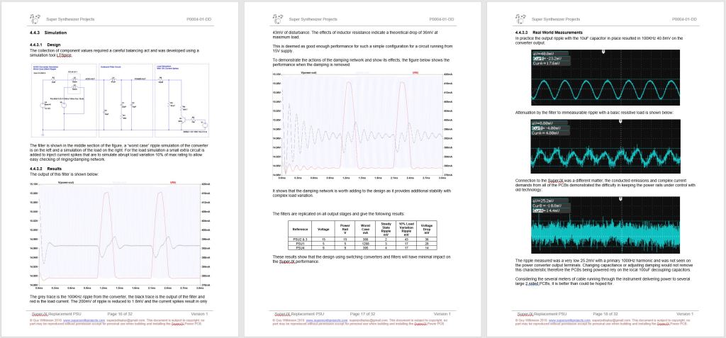
The design is described fully in a package of documentation.
Various data items can be found at the links below: Design Description, Schematic, Calculations & Test Results, Build & Fitting Recommendations, Bill of Materials.
- P0004-02-DD Design Description
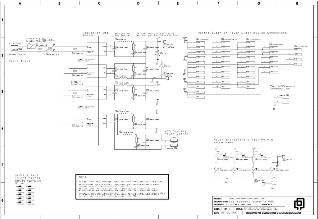
- P0004-01-SCH Schematic
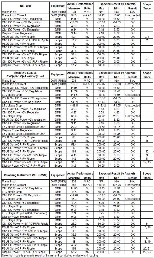
- P0004-01-DCT Design Calc-Test
- P0004-03-BFR Build-Fitting
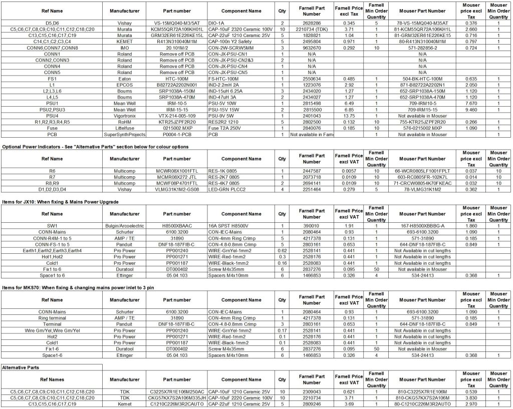
- P0004-06-BOM Bill Of Material (Incorporates JX8P versions and other options)
NOTE: The BOM contains all options for all types of configurations, please be sure to order the correct options to the base list. Electronics supply issues have pushed up prices since the BOM was created.
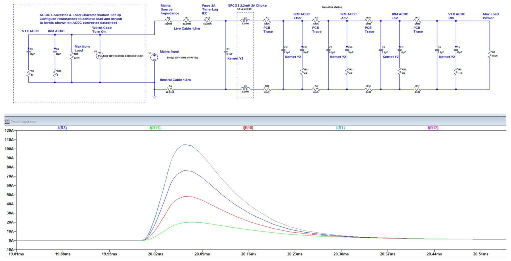
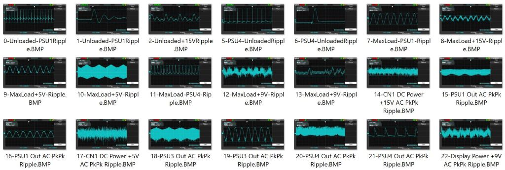
For more detailed information that is summarised in the design description, Simulations & Scope Traces of tests performed can be obtained here.
The detailed information published means that hobbyists can make judgements that the design is fit for purpose and that if they follow the build instructions carefully, then it will result in a secure and safe installation.
The JX8P version is not shown in the design data above with exception of the Bill of Material.
Obtaining Components
Caution is recommended if buying any ready made copies of this design as they may not use safe traceable components or have flawed design differences that affect electrical safety.
Be wary of counterfeit parts if not using traceable sources such as Digikey, Mouser, Farnell or RS Components. Low cost sources (such as eBay) for the capacitors and parts that connect to the mains are to be avoided. Damage to the instrument or electric shock can occur if care is not taken.
Note that the 9V Vigortronix Power Brick can be substituted for a 12V version if wanted, for example if using the power brick option from the SuperJX replacement VFD. If using 12V, the current consumption will be lower so same power rating (Watts) is acceptable.
Disclaimer
Users undertaking this DIY project need to have experience in electronics, mains appliance wiring and testing.
No liability can be undertaken by the author for the design, installation or damage to the instrument.
In the interests of electrical safety, installers and users are advised to take necessary steps such as Portable Appliance Testing (PAT) and adding a protective earth to the instrument.
Feedback Wanted
It would be awesome to receive constructive comments on this topic/page, if you have any, please email Guy at:

Copyright © 2022 Super Synth Projects, Guy Wilkinson

You must be logged in to post a comment.